Wilcox's Hot Air Machine
Source: an article from the Polytechnische Journal, 1863, Band 170, Nr. LXXXVIII.
Title: Wilcox's Heißluftmaschine
Author: Conrector G. Delabar.
© CC BY-NC-SA 3.0 DE
Among the various machines that I had the opportunity to visit and get to know better at last year's industrial exhibition in London, Wilcox's hot air machine was one of the engine that most caught my attention.
The same was sent to the exhibition by Messrs. Wilcox, Denison and Taylor of Westerley in Rhode Island, North America. Since no fire was allowed in the exhibition building, their representative, Mr. Denison, installed it in a house on the neighboring streets (No.4 Cromwell Lane) and put it into action.
There I repeatedly visited it and examined it during my stay in London.
Although an article has already been published in this journal about this machine, I think a further presentation provided with exact drawings will nevertheless be of interest to the readers.
As much as I know, the Wilcox's hot air engine has not yet been described in any other German technical journal.
As I undertake to deliver a detailed description of this utmost valuable hot air machine, I note that I am following a report of The Engineer of May 9, 1862, made about an article of Scientific American.
Following figures show:
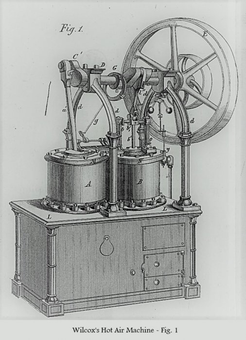
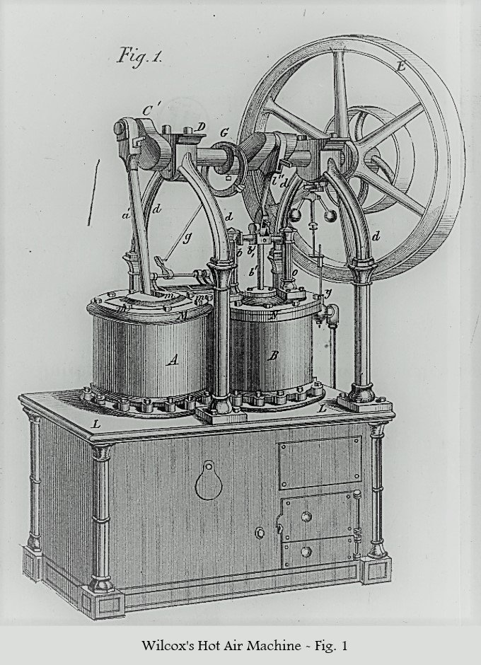
- Fig. 1: an elevation of the engine
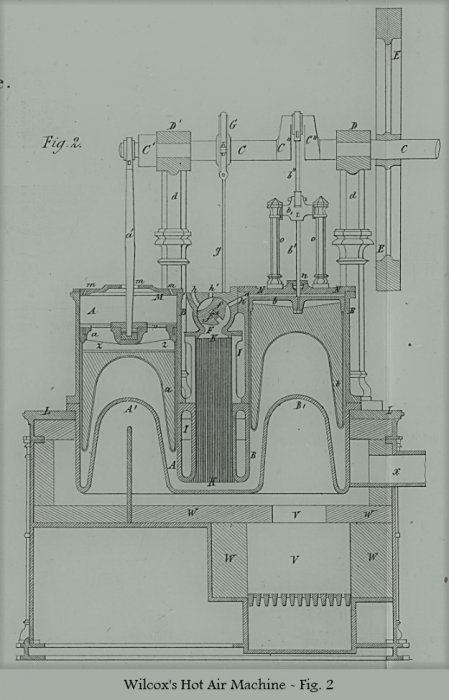
- Fig. 2: a sectional elevation of the same through the center of the cylinder
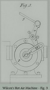
- Fig. 3: a view of the valve movement.


From these it is readily apparent that the Wilcox air engine has a complete different arrangement than the wellknown Ericsson air engine.
The furnace is intelligently placed within a subset and the crab-shaped mechanism that can be found on all other air engines known so far, is replaced by a very simple, solid, and effective construction.
As a result, since its invention and first introduction in America, this machine it said to have a growing success.
The machine arrangement is as follows:
A, A is the working cylinder and a is the single-acting working piston in the same; B, B the replacement and feed cylinder with b its piston. C, C is the main shaft, which has its support in the bearings D, D of the arcs d, d. C', C'' are the two cranks, which form almost a right angle with each other and by means of the piston rods a' and b', b'' and are in communication with the pistons a and b, which have the same diameter.
E is the flywheel. F is the valve sleeve communicating with the cylinder B and the external atmosphere, and f the valve, which, by means of the axis f' and the rod g, is regulated by the eccentric G, and opens and closes the channels h, h' and h'' as required by the engine.
I, I is a small chamber which communicates freely with F at the top, and at the bottom communicates with both cylinders A and B. It contains the regenerator K, which consists of thin metal plates and which aims to conserve heat.
Each cylinder A and B consist of two pieces and are fastened by means of flanges to the cover plate L. The lower pieces, which extend into the substructure of the furnace, are, together with the lower half of the chamber I, I cast in one piece and should be regarded as the actual heating surfaces.
As can be seen, the bottoms A' and B' of the cylinders are concave and extend to a considerable distance into the hollow spaces of the cylinders. This not only significantly increases their heating surface, but also considerably increases their resistance, so that they are much less exposed to the cracking by the internal pressure.
The upper end of the cylinder A is in connection with the outer air through openings m, m in the cover M, while the upper part of the cylinder B is closed by a tight patch cover plate N. By means of the valve f and the channels h' and h'', it communicates alternately with the external atmosphere and the regenerator.
The pistons a and b are slightly longer than their stroke. On their lower, heat-exposed side they are filled with a heat-non-conductive substance, whereby they are protected from heat loss.
The piston a is directly connected by a long rod a' to the crank C' and the shaft C. The piston b hangs on the piston rod b', which goes through the stuffing box n and is connected at the top with the crosshead b₁, that is guided by the buttresses o, o by which the movement is transmitted to the connecting rod b'' and thereby to the crank C'' and the axis C.
The valve f of peculiar form is so arranged that it causes, by means of the oscillating motion of the eccentric G, the connection through the channels h, h 'and h' between the upper part of the cylinder B, the regenerator K, and the outer atmosphere, as already indicated above.
The manner in which the valve or slider movement intervenes is shown in particular in fig. 3, where P is the side end of the valve sleeve, q is a slotted arm, which is attached to the end of the valve axis f''.
Another arm r is on one hand connected with the slotted arm q by means of the steel roller pin s, and one the other hand, sits on the shaft t which, in turn, receives the reciprocating rotating motion through the crank u and the rod g from the eccentric G.
The movement is further transferred by the crank r to the roller pin s, which slides back and forth in the slot of the arm g, and then further passed on by the latter to the valve axis f' and the valve f.
The dimensions and movements are arranged in such manner that the valve f mediates very quickly the movement from one position to another and then lingers in the individual positions of a revolution for a definite time.
The masonry W surrounds the combustion chamber V that has an opening in its center that allow the products of combustion to rise.
This way of construction protects the bottom B' of the cylinder B from the destructive effect of the intense heat of the combustion chamber, without any loss of heat. On the contrary, in this way the heat is held together and shared with the products of combustion, which then, at elevated temperature, fill the whole hollow space of the cylinder base, give off the heat uniformly, and leave the furnace through the smokestack x.
This uniform heat release and heat utilization is of great practical importance, because on it is mostly based the desired economy of fuel material and the durability of the metal used in the machine.
A further means of protection against the overheating of any part associated with the fire, is given by the self-acting regulator y, by which the expansion and evaporation of the mercury confined in a container of the furnace and used to more or less open or close a slide and damper in the smoke chamber.
This also helps to maintained the temperature as uniform as possible, and prevents the metal to heat beyond a certain allowable limit.
The upper part of the piston a, which in some respects resembles a roller, is provided with arms and moves up and down air tightly in the cylinder A.
There is a space z between the top of the piston a and it lower part made of a poor heat conductor material, that receives cold air from the outside, so that the temperature of the connection with the rod a', and the metal seal on the circumference is maintained at such a low temperature that the oil and grease of lubrication won't burn and will easily maintain their fluid state, fulfilling better the purpose of greasing.
Thence the cover M above A has, as already said, several openings m, m through which the air is sucked over a when the piston sinks, and expelled when it rises.
The temperature of the rubbing parts is kept so low by this simple means, that they can be lubricated sufficiently.
Clearly, it must not to be overlooked that precisely this way of optimizing the heat utilization when considering the piston a, is however disadvantageous. Nonetheless, the inventors and builders of the machine believe that with this method, under two evils, they have in any case avoided the larger.
The function of the cylinder B and the piston b is that the former, when the latter is going down, fills itself with fresh air. When the piston in turn goes up, the air is driven through the regenerator K where it is considerably preheated. It then reaches the lower end of B, where it is further heated to a high degree, and having gained a high pressure is transferred to the cylinder A where it gives up its mechanical work on the piston a.
As this piston is exposed to the pressure of the atmospheric air on its upper side and to the considerably increased pressure of the heated air on its lower side, it will of course, be driven up in proportion to the difference of the two-sided pressures.
The work is transmitted to the crank C' and the flywheel E by mean of the rod a'.
When piston a has reached the end of its stroke, the valve and rotary vane f changes its position in such a way that the external air communicates with the regenerator K through the channel h and the upper part of the cylinder B through the channels h 'and h''.
As a result the hot air, which is in both cylinders under the pistons a and b, flows through the regenerator K where it leaves a large part of its heat, and then escapes through the opening h into the atmosphere. At the same time the upper part of the Cylinders B receives a new charge of fresh air, which then during the next turn, undergoes the same conversion and utilization.
The sinking of the piston a hereby conveys the living force accumulated by the flywheel and the inertia of the rotating mass.
Figures 4 to 11 give a further detailed explanation of the relative movements of the two pistons in conjunction with the valve f, and their effect. The diagram above each figure shows the corresponding position of the cranks and the arrows indicate the direction in which the pistons move.

In Fig. 4 the working piston has just completed its course upwards and communicates its movement to the machine, while the valve f take the position that allows the heated air to escape to the atmosphere and opens the channel to the space above the piston b that has just done half its way down towards the bottom of the cylinder.
The space above b fills with cold air and the hot air under it and under the piston a escapes through the regenerator K into the atmosphere. This movement and work will be continued during the next quarter turn, as can be seen from Figures 5 and 6.

From Fig. 5 it is noted that during the sinking of the pistons a and b, no other force is applied than the one which is necessary to overcome the friction on both sides of both pistons, which are in free communication with the atmosphere, consequently exposed to the atmospheric pressure.
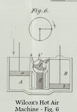
In the position Fig. 6 the piston b is positioned at the bottom and the cylinder B acquires a whole new refill of fresh air. The piston a, in turn, has reached its middle level, and the valve f has changed its position in such a way that the connection with the atmosphere is cut but the communication of the warm air with the spaces above and under and the piston b is open.
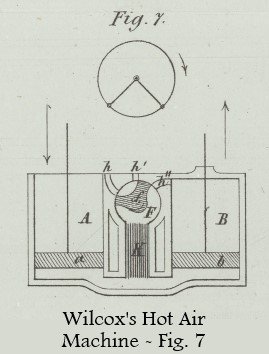
In the next quarter turn, Figs. 7 and 8, the working piston a continues to descend, the warm air below it being more and more compressed, and driven in part through the regenerator to the space above b. But before the piston a has fully reached its lower end, the piston b already begins to rise again, without encountering any resistance other than the frictional ones, as the air is set free to move on both sides of it.

In Fig. 8, the piston a has reached its lower end and the piston b has done half of its way up. Meanwhile, and consequently, the half of the renewed air passes from above the piston b through the regenerator and reaches the space under said piston, which now moves upwards at greatest speed, while conversely, the piston a meets the dead point of its crank movement, and is almost at rest.
The air arrived under the piston b is now considerably heated and expanded, thereby attaining the maximum of its tension.

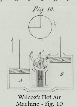
Until now, the movement of the machine is caused by the inertia, or the living power, of the flywheel. But at the beginning of the third quarter turn (Figs. 9 and 10), the direct work of the heated and expanded air exerts a much greater pressure on the bottom of the piston a than on its top. As a consequence the piston moves up and, by means of the rod a' and the crank C', the shaft C is rotated. This work continues in the last quarter revolution, Figs. 10, 11 and 4, with an air expansion decreasing in strength.
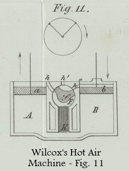
Before the piston a has reached its uppermost position and the piston b has begun its going down again, the position of the valve f changes again, and by means of the channels h, h' and h'', both spaces under piston a and b and the space above piston b are put in connection to the atmosphere, see Fig. 11, and the working piston a finishes the rest of its stroke in a dynamic equilibrium.
One revolution is now complete, the same movements and actions are repeated with each successive revolution.
In reality, one revolution is completed in 1/2 - 1/3 seconds, or said another way, the machine makes 120 - 180 rpm.
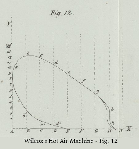
Fig. 12 shows a diagram of the mechanical work which is developed during one revolution. The distances traveled by the piston a during the individual time periods are given in abscissa and the corresponding pressure intensities (over atmospheric pressure) are plotted as vertical ordinates.
AJ represents half a revlolution and JA the other half.
The origin A of the coordinates AX and AY corresponds to the time moment when the piston a assumes the lowest level and the excess pressure of the heated air has reached the size Aa (of approximately 10 psi or 0.7 bar).
While the piston a travels the path AB and the crank C' thus covers half an eighths of a revolution, the excess pressure of the hot air reaches its maximum in B; Bb being about 13 psi or 0.9 bar.
Furthermore, while the piston a travels the path BH and the crank C' thus covers three eighths of a revolution, the excess pressure steadily decreases. At last, when the valve f is positioned in such manner that both sides of the piston a are connected with the atmosphere, the excess pressure suddenly falls almost to zero and will reach really this value when the piston will travel the path HJ, that is the crank C' will cover the last half an eighths of a revolution.
As a result, now half a revolution is done, which corresponds to the completion of the upward stroke of the piston a.
On its downward stroke during which it travels the first half of the distance JE, the piston a is in a dynamic equilibrium, and the excess pressure is therefore equal to zero.
In the second half of the downward stroke, in which the piston a travels the path EA, that is the crank C' travels the last quarter of that revolution, by the change in position of the valve f, the inflow of external air is cut and the internal air is exposed to the action of the fire. Its temperature and its tension increases again, and as the piston a continues its downward stroke and travels the paths ED, EC, EB, its excess pressure acquires the intensities Dd', Cc', Bb'. This excess pressure counteracts the movement of the piston a during this last quarter turn; the machine moves only thanks to the living force or inertia accumulated in the flywheel.
From these explanations, it becomes clear that the mechanical work corresponding to the upward stroke of the piston a is represented by the area A-a-b-c-d-e-f-g-h-J-A, and the one performed during the downward stroke is represented by the area A-a-b'-c'-d'-E-A. The real work, or net work, is obtained by subtracting the work done during the downward stroke to the work done during the upward stroke, and this is represented by the area a-b-c-d-e-f-g-h-J-E-d'-c'-b'-a; it illustrates the net work obtain for each revolution of the machine.
These machine operation and working conditions are based on the following air temperature used in the process: the temperature of the aspirated cold air is at most 100° F or 38° C, that of the heated and expanded air 600° F or 315° C, and that of the escaping air 260° F or 127° C. Since this latter temperature is also the highest temperature to which the valve f is exposed, there is no difficulty to have it properly lubricated or greased.
Finally, the most important advantages which are peculiar to the Wilcox hot air engine described here may still be emphasized. These are:
-
The gentle movement and low noise that distinguishes this machine against all other caloric machines. This has been readily noticed by anyone who saw the machine in action, and is due to the fact that both pistons have the same stroke, that transmit motion by means of cranks, and that there is no noisy valve such as those that can be found in other caloric engines.
-
The high speed and the associated increased work output. This fact is a consequence of the gentle, calm movement enabled by the care given thanks to the facilitated greasing. It is also a consequence of the included regenerator, and of the considerably increased heating surface, by means of which the trapped air can be heated very quickly.
-
The significant stability and durability of the machine. These qualities derive, first, from their advantageous and solid execution, and then from their gentle course, free from all shocks, from the use of only one single rotating valve instead of several pushing valves, and the effective protection of the heating surface from the direct action of the fire.
-
The considerable economy of fuel and its simple operation. The machine of two horsepower with a cylinder diameter of 18 '' consumed daily, that is during 10 working hours, only about 100 pounds (approx. 45 kg) of American anthracite coal. Per hour and horsepower, it is only about 5 pounds (approx. 2.3 kg), and according to Denison even only 4 English pounds (1.8 kg). As far as the operator is concerned, as I have convinced myself, the machine can be looked after by any attentive worker. Also, if necessary, the machine can be repaired by any experienced mechanic.
-
The complete security before exploding or shattering. At the given conditions of heating there is no danger at all in this respect. The machine is as safe as any other heater. An explosion as in steam boilers is out of question.
- The requirements. The machine uses only a small space and is not very tall. A one horse machine having a 12 inch cylinder merely requires a space of 24 inches to 38 inches (approx. 61 cm - 96 cm) and costs 2000 fr. A two horse machine with a 18 inch cylinder, on the other hand, requires a space of 32 inches to 50 inches (approx. 80 cm to 127 cm), and costs 2750 fr.