Wilcox's Hot Air or Caloric Engine
Source: an article from the Practical Mechanic's Journal, Vol 5, March 1st, 1861.
Title: Hot Air or Caloric Engine.
In another column of the Journal will be found a letter from our old correspondent and contributor, Mr. T.D. Stetson of New York, in which he refers to the “Wilcox air engine,” as being about to be manufactured on an extensive scale by several engineering firms in America. This air engine has been patented in this country (UK) in the name of Mr. J.H. Johnson.
A very favorable opinion was expressed by Professor Rankine on this class of engines, at one of the recent meetings of the Mechanical Engineers of Scotland. An abstract of the proceedings will be found in another part of the present number. We doubt not that many of our readers will peruse with interest the full particulars we here give of the “Wilcox engine.”
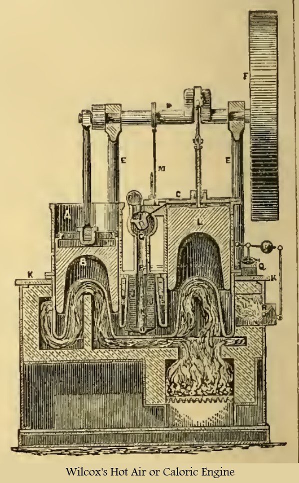
A is the working cylinder, and B the single acting working piston or plunger. C is the changing and supply cylinder, and L the piston working therein which, for the sake of simplicity of description, is for the present assumed to be a single light piston. D is the main shaft supported by the frame E, and having two cranks set nearly at right angles with each other. F is the fly-wheel, G the valve-chest communicating with the chamber H and provided with three ports.
Within this chest works the valve I. The small chamber H contains a regenerator J resting upon a central cone. At the lower end of the chamber H there are two nozzles or openings, and one of which opens into the cylinder A, and the other into the cylinder C. They form a communication between the chamber H and the cylinders.
The lower portions of the cylinders A and C, and chamber H, form the heating surfaces. The bed-plate K is supported by the brick-work, and the cylinders A and C are supported near their centres by a flange resting on the bed-plate K, their lower ends projecting into the flue below to receive the heat of the furnace.
The cylinder A is open at its upper end, whilst C is closed by a tight head. The pistons B and I are made somewhat longer than their stroke, and are filled with some non-conducting material in order to keep their upper sides as cool as possible. The piston B is connected by the rod with a crank over head, whilst the piston L has a rod passing through a stuffing box, and is connected by a short connecting rod with the other crank on the shaft D.
The valve I is turned so as to fit accurately the interior of the valve-chest G, and has a hollow throat of sufficient width to span two adjacent ports. This valve receives an oscillating or partially rotating motion, in the following manner: the axis of the valve passes through the valve-chest G, and it has a slotted lever on one end. In this slot works a roller which is carried on a lever I, which is in its turn moved by the eccentric-rod M.
The regenerator J consists of a hollow cylinder, composed of several thickness of wire-cloth. Its internal diameter is of the same area as the ports in the valve-chest, and its external diameter is greater according as the thickness of the regenerator is increased. As the course of the cold air is from the centre of the regenerator outwards, and as the air commences to receive heat and expand immediately upon entering the regenerator, and constantly receives more heat until it escapes at the periphery, much increased in volume, it is evident that the area of the passage-way should increase from the cold to the hot side.
This is effected by the peculiar construction of the regenerator, the outside of the wire cylinder having about double the circumference of the inside, and giving an area of passage way proportioned to the bulk of the air at all points, whether its motion be from the cold to the hot side or in the reverse direction. Within the regenerator is the cone N, filling it at the bottom and coining to an apex on a line with its top, thereby giving a large area for the cold air to pass in at the top, whilst, as it flows off laterally through the regenerator, a less area is required below. The taper of the cone N, gives the proper area at all points, and allows no more space for air than is absolutely required.
For the same reason, the chamber H tapers outwardly from the top to the bottom of the regenerator.
The same effect is produced with a regenerator made of thin plates of metal, by making the spaces either wider or thicker at the hot than at the cold end. A very convenient and desirable manner of constructing a regenerator of plates, in lieu of wire-cloth, is to prepare a series of thin plates, much broader at one side than at the other, but of uniform thickness throughout, and riveting or bolting them together with washers of a uniform thickness interposed between each plate and the next. The regenerator thus formed may then be tightly fitted into a case of corresponding wedge-like form, the narrow end being uppermost, or towards the cold end of the cylinder.
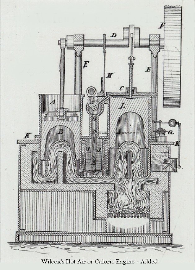
(This second figure was found in the Polytechnischen Journals that reports about this same article. Some engine details can be better viewed ).
The vessel O rests upon the bottom of the chamber H, so as to be heated as nearly as possible to the same temperature as the metal upon which it lies.
From this vessel a small tube P passes upwards through the cone N, and thence through the side of the valve-chest G, and is connected with the chamber Q below the elastic diaphragm fitted therein. Upon this diaphragm rests a small plate, having a rod connected with a weighted lever. A link connects this lever to another lever on the end of the spindle of the damper R, in the flue.
The cylinder or vessel O is filled with some fluid that vaporises at a high temperature, such as mercury, which will commence evaporating at about 650° F (approx. 343° C). When this temperature is attained, a portion of the fluid will be forced through the tube P, raising the diaphragm in the chamber Q, and the lever by which means the damper R is closed, the combustion in the furnace is checked, and the temperature of the heating surfaces reduced.
As the temperature falls, a portion of the vapour of mercury is condensed, and the diaphragm sinks until the damper B is again opened and the fire quickened. Thus the temperature of the beating surfaces is uniformly maintained at about the point which the metal can safely bear. It is evident that the temperature of the heating surfaces can also be regulated by connecting the lever with a slide arranged to admit cold air above the fire, which will cool the heaters both by direct contact with them and also by filling the chimney with cold air, which will retard or check the draft.
This portion of the engine is of great practical importance, as the change effected in the structure of the metal, in consequence of being too intensely heated, has caused the failure of some otherwise successful hot-air engines.
It must be observed that the vessel O is not in contact with the products of combustion, and that the motion of the diaphragm in the chamber Q, by lever and damper R, does not necessarily, and should not in many instances, correspond with the fluctuations in the heat of the fire. The vessel O is within the chamber H and is in contact with the inner side of the heating surfaces at its base.
Now, the heat of the products of combustion is only one of the elements which tends to control the temperature of the vessel O, the other being the power with which the engine is working. If the engine be working very moderately, and with little or no load, the temperature of the vessel O may rise very nearly to the same point as that of the products of combustion; but when it is working under the opposite conditions, the larger quantity of air which is warmed in any given period tends to cool the interior of the heating surfaces, and in order to maintain a uniform heat in the metal it is necessary that the temperature on the exterior be considerably higher than before.
The apparatus is therefore intended to maintain a uniform temperature - not in the gases either on the exterior or interior, but in the metal of the heating surfaces - and to produce this result by so regulating the draft through the fire as to supply just sufficient heat under all conditions.
This feature of the invention is especially important when the engine is frequently stopped, as without it the metal is liable to become heated to a bright red heat in a short time, and to become too much or too suddenly cooled when it is again put in motion.
The furnace is supplied with fuel through a suitable fire-door, and the products of combustion pass from the furnace and circulate around the bottoms and sides of the cylinders, and finally escape to the chimney through the fine, in which the damper R is fitted. By allowing the products of combustion to circulate in contact with the end of the working cylinder, as well as with that of the changing cylinder, the inventor is enabled greatly to increase the area of the heating surface without, at the same time, increasing waste space.
If the air were passed through a pipe of sufficient length to give the same amount of heating surface as the cylinder bottom, the pipe must have sufficient area throughout its length to allow a free passage of the air, which involves an amount of waste space that would seriously reduce the power of the engine; but in this invention the lower end of the piston is so formed as to fit the cylinder bottom, and as at the end of its stroke it comes within a short distance of it, the waste space is comparatively small.
In this engine a measure of air is transferred from the cold to the hot side of the changing piston, and by its expansion the working piston is forced up, and power is imparted to the engine. But at or about the termination of the up stroke of the working piston the difference becomes apparent, for at this juncture the valve I by its rotation, opens the eduction port, and allows the air to escape, while it also opens the induction port. As the changing piston descends, the space above it is filled by a supply of fresh (or relatively fresh) air drawn either from the atmosphere or from a reservoir.
When this engine is worked with the air at only about the atmospheric pressure the fresh air is drawn directly from the atmosphere, as represented, and the hot air beneath, the two pistons is discharged and blown away.
But it can, if desired, be worked in the same manner under a higher pressure, by connecting a reservoir with the eduction and induction ports. In such case, air is compressed by a pump until it fills the reservoir to any pressure desired, and the pressure within the engine will correspond therewith, and thus produce a greater effect at each stroke; but when worked in this manner, the engine must be provided with a refrigerator analogous in structure, though not in arrangement and effect equivalent, to Stirling’s.
This engine differs from Stirling’s in the following points.
Stirling’s alternately transfers the same air from the cold to the hot side of the changing-piston, and vice versa, whilst Wilcox's discharges the hot air and draws in a supply of other air at each stroke.
Stirling’s involves a loss of space in the refrigerator, which is analogous in effect to that caused by what is known as a "clearance" in steam engineering, which loss Wilcox avoids; because, when the ports communicate with the atmosphere, no refrigerator is employed, and when they communicate with a reservoir of compressed air, the refrigerator is outside of or beyond the valve, and its pipes and fittings form a portion of the reservoir, and not a portion of the space within the cylinder. The space involved in the refrigerator is not therefore equivalent to clearance in this engine, and is of no effect whatever in the same.
The peculiar motions of the two pistons in relation to each other could be effected by means of cams, but cranks afford a smoother motion and allow of more rapid action, from the tightness at which the parts can be maintained, and the very gradual manner in which the changes occur. For this reason the two cranks are placed at nearly right angles with each other. The inventor finds that the engine performs best when one crank is about 75° forward of the other.
In this engine the pressure acts only in one direction to force the piston up, the momentum of the fly-wheel serving to complete the downward stroke against a gradually increasing hack pressure; but by obvious means two air engines of the character herein represented may be combined so as to form a double-acting engine.
In operating the engine as above described, a considerable loss of effect is experienced, from the fact that heat is conveyed through the material of the changing piston and imparted to the air immediately on its entering the space above it. The heat thus imparted to the air first received causes it to expand and obstruct the ingress of that which should follow. The result of this is, that less air is received than would he required in a cold state to fill the space formed by the sinking of the changing piston, and less power is therefore developed by the engine.
It is also found that much heat is conveyed upward through the working piston, and that the top of the same becomes so highly heated that the lubricating material is injuriously affected, unless much care is taken to prevent it. This evil can only be partially remedied by increasing the thickness of the piston, and any such increase of the material involves serious difficulties by increasing the size of the engine and the inertia of the parts. The changing piston L is therefore constructed in two parts, as shown in the figure. The lower part is made hollow, and is filled with ashes or other good non-conducting material, and is of slightly less diameter than the cylinder, so that a narrow annular space is left between its periphery and the interior of the cylinder C.
The two parts are secured rigidly together by webs, or other equivalent connections; but the connecting parts are not of sufficient area to be of much effect in conveying heat from one to the other. In the space between the two parts of the piston an annular or other self-acting valve is provided, which allows the air to flow at pleasure from the upper or cold side of the piston L, to the lower or hot side, but prevents its return.
The operation of the engine as thus arranged is as follows:
Upon the descent of the changing piston L the air is drawn in through the valve I; but when it rises, instead of all the air passing through the valve-chest I and the regenerator H, a portion passes through the valve between the two parts of the lower piston, and thence around the outside of the part, where it is heated and expanded, and serves to impel the engine by forcing up the piston. When its useful effect is ended, it is discharged through the valve I, the valve at the top of the Piston L, closing to prevent its returning again to the top of the cylinder C.
By this conveyance of a portion of the inducted air between the lower part and the upper part of the changing piston, the heat which is conducted or radiated upwards into the top part is removed by the stream of air which is passing; and the inducted air, instead of playing directly upon the heated top of the part and becoming prematurely expanded, with the ill effect of thereby preventing the ingress of the full and proper quantity of air, plays upon a cool surface on the top of the part, and is not allowed to come in contact with the lower part until the piston L begins to ascend.
The proportion of the air which it is necessary to pass through the piston in this way for this purpose, is determined by the amount to which the valve at the upper part of the piston L is allowed to open.
In the working piston B, a clear space extends across the upper part of the piston, with the exception of a thin shell at the periphery. The lower extremity of the connecting-rod is joined to the piston — not through the aid of a continuous plate, as heretofore, but of an open frame, which extends from the centre to the circumference, forming a strong connection between the rod and the lower portion of the piston B, but with liberal openings through which the air may circulate.
As the piston B reciprocates rapidly, the agitation of the air contained in the upper space and of the air immediately above is sufficient to induce a partial displacement of the air at each stroke, so that the space is always filled with air at a comparatively low temperature, which, by its circulation, conveys away the heat conducted upward to the rubbing surfaces.
If no air space existed in the piston, or if it were enclosed by means of a tight plate above, so that the contents of the space would not be displaced in part at each stroke, the rubbing surfaces at the top of the piston would have to sustain a much higher temperature, the heat at the bottom of the piston diffusing itself more uniformly throughout its whole substance.
The thin tube or sleeve surrounding the rod of the piston L is an arrangement which the inventor has devised for actuating the valve at the top of the piston L, in lieu of or additional to a spring. The friction of the packing in the stuffing-box is thus rendered available for operating the valve. As the piston L ascends, this friction tends to open the valve; and the moment the piston begins to descend, the friction, either alone or acting in conjunction with a spring, closes the valve, and hold it tightly closed during the entire descent.
- The advantages obtained by this invention are, that pumps and coolers are dispensed with, and, at the same time, the engine is run at high speeds without noise.
- By employing the ends of both the working and the changing cylinders as heating surfaces, space is economised in proportion, and the power of the engine proportionably increased.
- The heat regulator protects the heating surfaces from the destructive effects of an extremely high temperature and regulates the fire, thereby keeping the interior of the heating surfaces at a nearly uniform degree of heat under all conditions. The area of the passage-way through the regenerator is proportioned to the bulk of the air at all points, and the resistance to the passage of the air is much reduced.
- The valve I performs the threefold office of induction, eduction, and equilibrium valve with less friction and less liability to derangement than any means previously introduced.
- The upper part of the changing piston and cylinder are kept at a comparatively low temperature by the circulation of a portion of the cool air through the double piston L, allowing the full amount of cool air to be taken in at each stroke, whilst, at the same time, the full effect of the regenerator is obtained, or very nearly so.
- The free circulation of air into the open space in the upper part of the working piston, serves also to keep the rubbing surfaces cool, and prevents also the burning of the lubricating material.