Parkinson and Crossley's Air Engine
Source: History and Progress of the Steam Engine
Date: 1832
Title: Parkinson and Crossley's Air Engine
Author: Elijah Galloway
Patent Air Engine, by Messrs. Parkinson and Crossley, of the City Road, London 1828
This invention is another modification of machinery for rendering available to useful purposes the elastic force of air, in the construction of a motive engine.
We have seen two models of these air engines at work, in which two distinct arrangements of the apparatus are introduced.
The operations of heating and cooling the air are performed so rapidly by them, as to cause one hundred and fifty strokes of the piston in a single engine to be made per minute.
The patentees not having yet completed their experiments on the large scale, we shall at present confine our attention to the specification of their patent lately enrolled, from which we make the following abridged extracts.
The power of this engine is derived from the heating and cooling of air, in an air-tight vessel, which the patentees term a differential vessel; a portion of this vessel being exposed to heat, and another to cold, externally.
Inside the differential vessel is placed another of a similar figure, called a transferrer; this being moved from the hot to the cold parts of the differential vessel, and from the cold to the hot, alternately, transfers the air, and subjects it to the variations of temperature, as it passes along the internal surface of the differential vessel; and thus, by the expansion and contraction of the air, produces force for giving motion to machinery.
The patentees do not claim to be the first discoverers of obtaining power by the alternate contraction and expansion of the air, by the processes of heating and cooling, but in the peculiarity of their method of effecting it.
One of the most approved forms for this purpose we shall now proceed to describe, with reference to the accompanying drawings, figs. 1 and 2, which are upon a scale of two-thirds of an inch (approx. 1.70 cm) to the foot (approx. 30.5 cm).
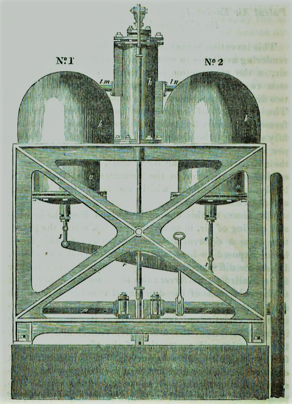
Fig. 1, shows a front elevation of so much of an engine as is necessary to explain the invention; fig. 2, is an end elevation; and fig. 3, is a section of a differential vessel and its transferrer, exhibiting also a mode of heating and cooling the differential vessel.
The same letters in each figure, where they occur, refer to the same parts.
The differential vessel, a a, is of the form of a hollow cylinder, with close convex ends, of such a length as to preserve an essential difference in the temperature between one end and the other, and nearly one half of it being subject to a hot, and nearly the other half to a cold medium.
The vessel has a stuffing-box at the end f, and at the other end is an opening of pipe lm, or ln, for the purpose of forming a communication with the working cylinder and piston.
The transferrer bb is in this instance made a hollow vessel, air-tight, and so much shorter, as to leave a sufficient space in the differential vessel for containing a volume of air, which, when expanded by heat, and passing through the pipe lm or ln, will also fill the working cylinder, and force the piston from one end of it to the other; the transferrer is also made, only so much less in diameter, as to admit of its being moved freely from one end of the differential vessel to the other.
To one end of the transferrer is fixed a rod e, passing through a stuffing-box f, for the purpose of moving it from one end of the differential vessel to the other, thereby causing the air to pass in a thin stratum against its hot and cold parts, alternately; thus producing the force or power to be employed against the working piston.
The rod g, (fig. 3,) which is fixed on the upper part of the differential vessel, is intended to guide the transferrer in its proper direction, by means of a tube, which is inserted in the upper end of the transferrer for that purpose, the lower end of which is made air-tight.

A differential vessel, constructed on this plan, may be applied to the purpose of working a single engine, acting only on one side of the working piston, after the manner of the well-known steam engines called single or atmospheric engines; but, in most cases, the patentees prefer the use of their differential vessels, as pointed out in the drawings fig. 1 and 2, directing the power alternately on each side of the working piston, after the manner of double steam engines.
Motion is given to the transferrer by means of the eccentric o, in the shaft p, being connected with the beam r, which beam is connected to the rods e, of the transferrers, by the links s s. The working cylinder n, with its piston, side-rods, cranks, shaft, and fly-wheel and eccentric motion, are the same as those commonly used in steam engines, and therefore require no particular description.
The pipe l m, communicates the differential vessel, No. 1, with the top of the cylinder; ad the pipe l n, communicates the differential vessel, No. 2, with the bottom of the cylinder.
The operation of the engine will be as follows:
Supposing the eccentric disconnected from the beam r, and the upper parts of the differential vessels heated, and their lower parts cold, and the transferrers of the two differential vessels placed by hand in the situations shown in the drawing, and the volume of air occupying the hot part of the differential vessel No. 2, and being increased in elasticity in proportion to its temperature, whilst the volume of air in the differential vessel No. 1, is occupying the coldest part, the working piston will be forced upwards, by a power corresponding with the difference of elastic force of the air in the two differential vessels; and when the working piston has been forced to the top, the situation of the transferrers should be reversed by hand, so that the air in the differential vessel No. 1, will occupy the hot part, and communicate its force to the upper side of the working piston, and thereby produce a returning stroke; and the eccentric being then by hand re-connected with the beams, the alternate expansion and contraction of the air in the two differential vessels, will keep the engine in motion; and thus, by working the transferrers the same way as the valve in steam engines, the engine may be either put in motion of stopped.
For the purpose of heating the vessels, the patentees prefer the employment of inflammable gas, as it may be easily procured in all the principal towns in the kingdom; and by using compressed gas in portable vessels, the engine will be better adapted to locomotive purposes.
As the street mains during the day-time, although charged, are generally charged at so light a pressure that the supply would be inadequate, the machine commonly called a gas-meter may be employed as a rotary pump for obtaining a supply, by connecting with its axis a train of wheel-work, with a spring or weight, to be wound up after the manner of clocks or time-pieces, giving to the meter a rotary motion.
The mechanism of clocks being so generally understood it is unnecessary to describe it here; it should, however, be observed, as the axis of the meter is below surface of the water in the meter, one end of it should always project through a stuffing-box, in order to protect the mechanism from corrosion. The instrument called a gas-governor should be added to the meter, for the purpose of correcting any irregularity in the flow of the gas.
The patentees do not claim by this patent the gas-meter and gas-governor, nor their combination with clock-work, but that combination of the gas-meter with clock-work, or with the gas-governor, for the obtaining of a supply of gas from the street mains, which is made up by them with parts of the machinery of their engine, subject to the rights of the patentee of the gas-meter and gas-governor.
The use of gas to this engine, and the application of the means described for obtaining a supply, enable the patentees to furnish a compact power engine, not requiring the constant attendance of a fire-man, and adapted to situations where sufficient space could not be appropriated for an engine requiring a boiler and coal-house, and where the smoke of such engines might be deemed a nuisance.
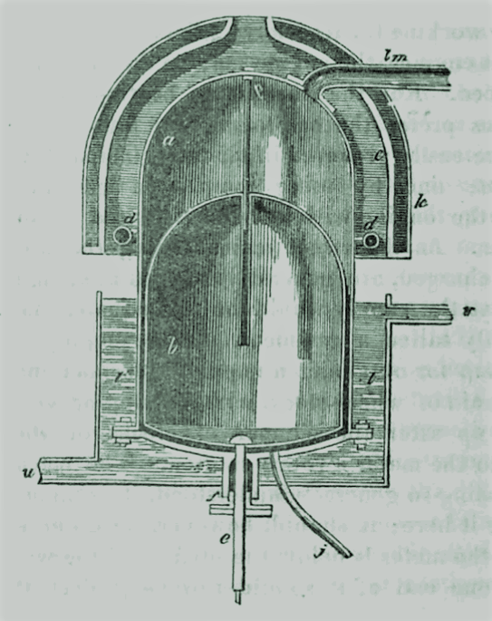
A mode of applying gas for heating the differential vessel, is shown at fig. 3. d d, is a hollow ring, surrounding the differential vessel, and communicating with the tube by which the gas is supplied; this ring is perforated, for the emission of jets of gas to flow, when ignited, all around, and against the differential vessel, or nearly so; c c, is an iron casing for directing the heat to the differential vessel, which casing is open at the bottom, for the admission of air, having also an opening at top, to serve as a chimney or flue; h, is an outer covering of polished metal, of about two or three inches (aprox. 5.5 cm to 7.6 cm) more in diameter than the casing c c, for the purpose of lessening the radiation of the heat.
The working cylinder h, may be kept hot by means of a current of heated air being conducted to it from the flues of the differential vessels; the arrangement for which being so easily understood, it is purposely omitted in the drawings.
In fig. 3, t t, represent the differential vessel, as placed in a cistern of cold water, with a constant current running ¡n at the bottom, u, against the differential vessel, and passing off at the top v.
In situations where a sufficient quantity of water cannot be obtained for procuring the desired effect in this way, other well-known means of cooling vessels may be resorted to.
To increase the power of the engine, it is proposed to increase the density of the air, by a common forcing-pump worked by the engines, and connected with the differential vessels; and as some leakage of air may be anticipated at the high pressures, the addition of the pump is necessary, and may be connected with the differential vessel by the tube j.
This pump should be provided with any of the well-known means of adapting the length of the stroke to the loss of air by leakage. In starting the engine, this pump may be disengaged from the engine, and worked by hand, for charging the differential vessels with air of the intended density.
A safety-valve should be connected with the differential vessels, and adjusted so as to let off any excess of air above that which is required.
The speed or power of the engine may be regulated by increasing or diminishing the supply of gas, or other source of heat, by connecting a governor similar to that used in steam engines, with a valve or stop-cock in the pipe supplying the gas, or with a damper in a flue, or with valves plated in the pipes lm and ln, regulating the ingress or egress of the rarified air to and from the working cylinder.
The differential vessels and transferrers may be constructed upon the same principle in various forms, either cylindrical, cubical, or spherical; and they may be placed in vertical, inclined, or horizontal positions.
The patentees mention several modifications in their specification, which it is unnecessary here to describe. The deviations in the shape will of course require different methods of applying the heat. The patentees do not confine themselves to the use of gas only, as the source of heat; in some cases, even steam may be adopted as a medium of communicating caloric; but a preference is given to the apparatus particularly described and delineated in the engravings.