Wilcox Engine of 1860
The Wilcox engine is one of the most elegant hot air engine that proved to work nicely.
 |
|
| Inventor | Stephen Wilcox, Jr. of Westerly, county of Washington and State of Rhode Island,. |
| Country | America |
| Year | 1860 |
| Patent | Yes |
| Operation | Open cycle |
| Combustion | External |
| Engine type | Two cylinders |
| Working piston | Single acting |
| Output | 0.5 HP to 2 hp |
| Fuel consumption | Coal, gaz, wood |
History
The force derivable from the expansion of atmospheric air by heat, although it has failed to compete successfully with steam in cases where much power is required, has within a few decades, established itself as practically successful in furnishing a convenient motor where small power is required. In 1860, there was in practical operation, hundreds of engines deriving their power solely from this source.
At that time, the great and important considerations of safety, both to human life and to the building in which it is operated, and the little skill and labor required of its attendant have established for the hot air engine, or rather for hot air motors of some kind, a demand which increased steadily. A steam engine, of necessity, requires a boiler, and this dangerous adjunct, however small it may be, involves either a necessity for competent, and, consequently expensive, attendance, or a risk of explosion. Usually, both these evils attend in a greater or less degree the employment of steam power, and both become more serious as the size or power of the apparatus is diminished.
These evils are avoided by the use of hot air engines.
Objections to the hot air engines in general use are slowness of motion, great bulk, and for some air engines the clatter while operating.
The engine Wilcox hot air engine which forms the subject of these illustrations has been developed during 1859-1860, and is measurably free from these objections. On those days it was already in practical use in a considerable number of printing establishments and small manufactories, making its revolutions with uniformity equal to the best steam engines, while the only noise emitted was due to the induction and exhaustion of the air.
Robert Stirling succeeded some twenty years ago, in producing an air engine, which was the first practically successful one, and which forms the basis of the invention we are about to describe.
In contrary of the Stirling engine, the Wilcox's hot air engine was freed from the usual flaws encountered in hot air engines and proved to be very successful.
Wilcox's enhanced hot air engine
Fig. 1 is a perspective view of the engine, which its furnace complete.
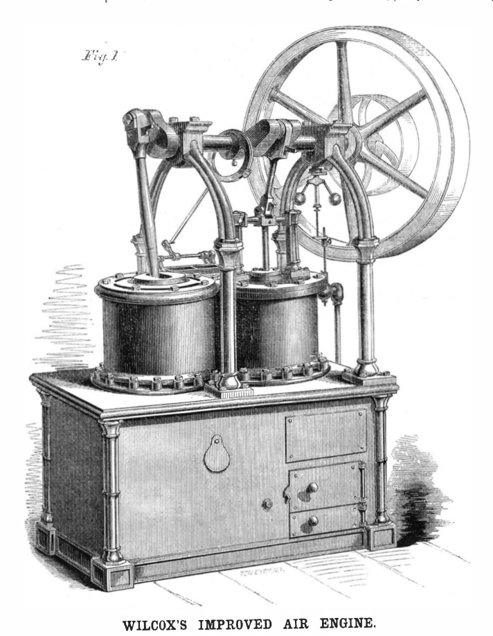
Fig. 2 is a vertical section, with the parts somewhat differently arranged, the better to show their arranged, the better to show their peculiar action.
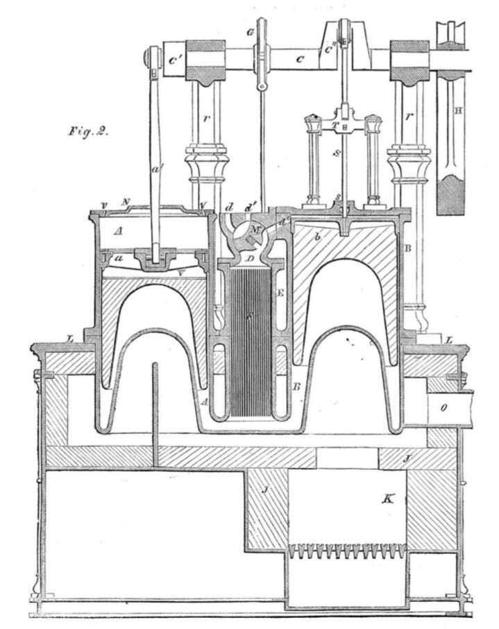
A is a working cylinder, and α a single-acting working piston. B is the changing and supply cylinder, and b the piston working therein. C is the main shaft, supported by the arches r, r, and having two cranks C1 and C2 set nearly at right angles with each other, and connected to the two pistons, α and b, as represented. H is the flywheel. D is the valve box communicating with the cylinder B, and with the external atmosphere through three ports, d d1 d2. M is a valve to open and close these ports at pleasure.
A well thought regenerator
E is a small chamber communicating freely with D, and with the lower end of both cylinders, and containing the regenerator or economizer F, composed of thin metal plates.
A and B are attached by a flange near their centers to the bed plate L. The lower portion of both the cylinders and of the chamber E, are cast in one piece, and project into the flue below forming the heating surface. The bottoms of the cylinders are concave and extend a considerable distance upward, thereby greatly increasing the extent of heating surface and also rendering them less liable to spring under the internal pressure.
The upper end of the cylinder A, communicates freely with the external atmosphere through openings in its cover N, while the upper end of the cylinder B is closed by a tight head, and is made to communicate alternately with the atmosphere and the economizer (or regenerator) chamber E, by the action of the valve. Pistons α and b are made somewhat longer than their stroke, and are filled with a non-conducting substance, to prevent the heat, to which their lower sides are exposed, from being communicated to their upper sides.
A long rod a' connects the piston α, directly with the crank C1, while the piston b, has a rod S, passing through a stuffing box s, and keyed to a cross head T.
A short rod connects T with the crank C2. The valve M, has a hollow throat of sufficient width to span ports of d’ and d’’, and the space between, and receives an oscillating or partially rotating motion, from the eccentric, G.
K is the furnace. The firebrick J, extends over the furnace, allowing the hot products of combustion to rise through a liberal opening in the center. This construction protects the edges of the cylinder bottom from the destructive efforts of the intense radiant heat, but involves to ultimate loss of calorific effect; the heat thus retained being found in an increased temperature of the products of combustion. These latter flow around the whole base and apply the heat uniformly, and then pass to the chimney through the flue O.
This matter — the uniform application of heat — is one of the great practical importance, tending materially to promote the durability of the metal. As a further preventive of over heating any part, and automatic regulator, by which the expansion, or rather the vaporization of mercury contained in a vessel in the heater is caused to correspondingly close a damper in the flue has been applied and found to maintain a very uniform temperature, preventing the heat of the metal from rising under any circumstances above a proper moderate degree.
The piston α, is made with arms somewhat like a pulley, and a space V, left between it and the filling below, so that the cool air in the top of A circulates around the joint by which the connecting rod a’, is attached, and thereby keeps it and the metallic packing at so low a temperature as not to burn the oil used for lubrication. As a further means of effecting this object, a cover N is placed upon A, having openings, v v, through which the air above α is forced out as the piston rises, and a fresh supply drawn in as it descends. By this sample means the temperature of the rubbing parts is kept so low that they may be readily and perfectly lubricated.
Fig. 3 shows the valve motion. D is the end of the valve box, and m a slotted arm keyed on the end of the axis of the valve. I is an arm fixed upon a rockshaft, W, which receives a reciprocating motion from the eccentric, G, Fig. 2, through the rod, g, and arm, w.
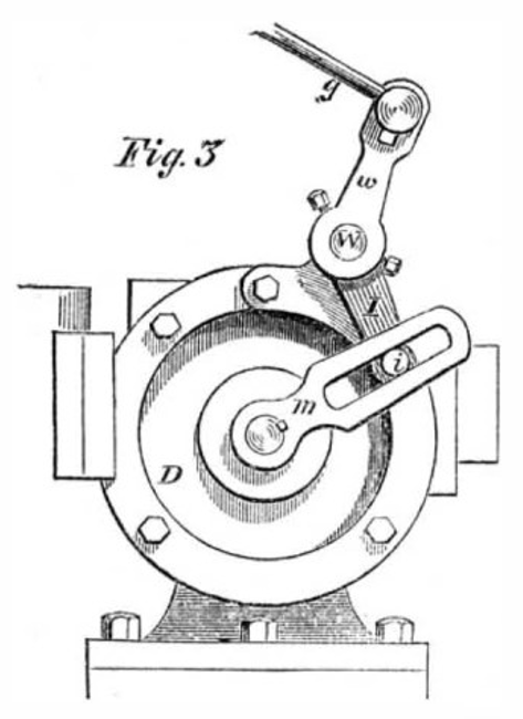
A steel roller i, carried on I, plays within the slot in m, and the proportions and motions are so arranged that the valve is thrown very quickly from one position to the other, and retained for a period nearly stationary at the end of each movement. This is accomplished by the peculiar action of the roller i, working in the slotted arm m.
The role of the valve box
The function of the cylinder B, and the piston b, working therein, is to take in a supply of cool air for the atmosphere through the valve, and then, when it arises, transfer this air through the regenerator into the hot end of B, where it is expanded and its pressure is much increased. The piston a being exposed to the atmospheric pressure on its upper side, and to the increased pressure obtaining in B on its underside, is forced upward, and imparts motion to the shaft C, and flywheel H. When α has been driven to the extent of its motion, the valve M is changed, and the heated air now filling both B and A is allowed to flow through the regenerator, where it parts with much of its caloric, and escape through the port d, into the atmosphere. The momentum of the flywheel then returns the piston α to its former position, and in the meantime b has taken in a fresh supply of air, to be changed over the propel through another stroke.
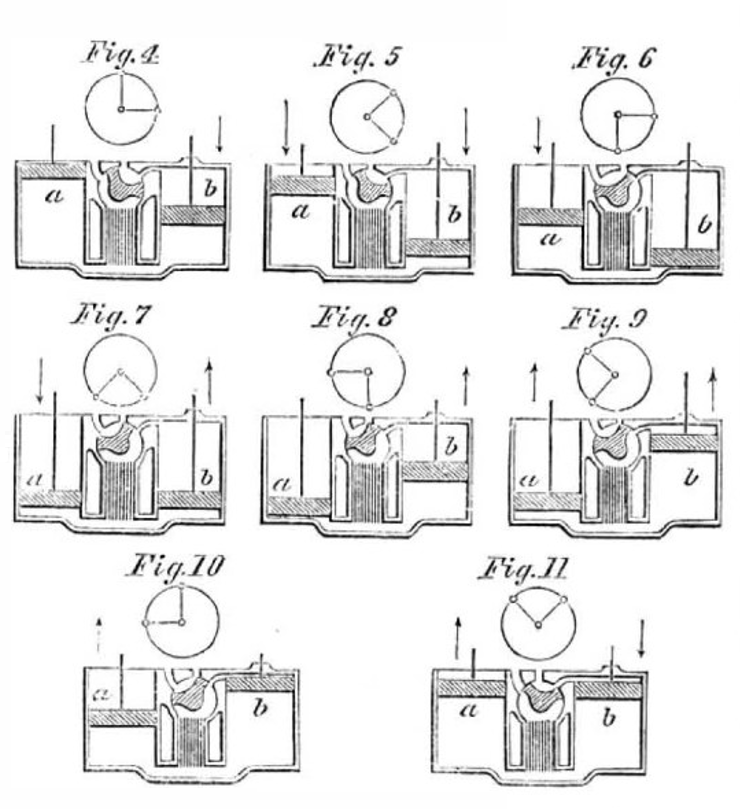
This action and the relative motions of the two pistons and valve will be seen by means of Figures 4, 5, 6, 7, 8, 9, 10 and 11.
The circular diagram over each figure shows the corresponding position of the cranks, and the arrows indicate the direction in which the pistons are moving. In Fig. 4 the piston has completed it up-stroke and imparted motion to the engine; the valve is in position to allow the heated air to escape, and maintain a communication between the atmosphere, and the space above the piston b, which has made half its down stroke, the space above it being filled with cool air and the hot air below escaping through the generator.
This action continues through the next quarter of a revolution, as is shown by Figs. 5 and 6.
It will be seen that no power is expended in this operation, excepting that required to overcome friction, both sides of both the pistons being in free communication with the atmosphere, and consequently exposed to atmospheric pressure.
At the position shown in Fig. 6, the piston b, having taken in a fully supply of cool air, and α having made half its down stroke, the valve is changed so as to cut off the communication with the external air, and open a passage between the space above and below b. As α continues to descend, it compresses the warm air beneath it and that contained in the regenerator, forcing a portion over into the space above b. The piston b, commences, to ascend but encountered no resistance, as there is a free communication between its two sides.
At Fig. 8 the piston α has been forced to the end of its stroke by the momentum of the fly-wheel, against the increasing pressure of the air within, which pressure acts the same as “cushioning” in a stream engine; b continues to rise and has changed one half the air above it around through the regenerator into the space beneath, by which process the air is heated and its pressure greatly increased.
It will be seen that at this point b is moving at its highest velocity, while α is nearly stationary or at its “dead point”; the air above b is therefore mostly changed to the hot end, while α remains within a short distance of the end of its stroke; and therefore, when α commences to ascend, it has a pressure beneath it much greater than that which resisted its descent. This pressure forces it up and imparts motion to the engine, while the pistons are alternately assuming the position shown in Figs. 9, 10, and 11. At this latter point the valve is changed as shown in the figure, and the heated air allowed to escape, the piston α, performing the remainder of its stroke in equilibrium.
One revolution is now complete, and this process is repeated at each revolution. In practice, this revolution is made in one half of a second, or one hundred and twenty in a minute.
Calculated energy

Fig. 12 is a diagram of energy calculated for this engine from the following data, which were found in practice to be very nearly attained.
- Temperature of cool air: 100° F (approx. 38° C)
- Temperature of heated air: 600° F (approx. 315° C)
- Proportion of lost space to volume of working air: 0.5
- Angle of cranks 90°
- Area of α = area of b.
- Compression = one half stroke
Under these conditions it was found in practice that the escaping air temperature is 260° F (approx. 127° C), and as that is the highest to which the valve M, was ever exposed, there was found to be no difficulty in keeping this valve properly lubricated.
The advantages claimed for this engine were:
- Smoothness of motion and little noise. These arise from the fact that the two pistons have the same stroke and are driven by crank motions, and from the absence of puppet or other noisy valves.
- The high speed and consequent increase of power. This is due to the smoothness of motion, the use of the regenerator and the large amount of heating surface, by which the air is heated with sufficient rapidity. The power of air engines is limited by the amount of heating surface, in the same manner as is that of steam engines.
- Durability. This arises from the smoothness of motion, absence of percussions, the use of only one valve, and the protection of the heating surface from the direct action of the fire.
- Economy of fuel and attendance.
This improved hot air engine was the subject of several patents issued to Stephen Wilcox, Jr., which bear the following dates: May 3, 1859, Feb. 16, 1860, and Nov. 20, 1860. The first patent was reissued in two separate patents, Nov. 20, 1860. It has also been patented in Great Britain and France.
Archives
| Archives |
|---|
| Practical Mechanic's Journal, Vol 5, March 1st, 1861 |
| Polytechnische Journal, 1863, Band 170, Nr. LXXXVIII |