A Hot Air Engine History
Source: After Knight's - American Mechanical Dictionary
Date: 1874
Author: Edward Knight
For more than a century the attention of mechanicians has been directed to means for making air and gases available in driving machinery. The inventions resulting from these efforts have led in different directions, or to different sets of specific means.
Some have attempted to make available the expansion of air, previously mechanically condensed and stored in reservoirs. It was not understood, apparently, that the valuable effect would only be equal to the force employed in condensing the air, minus some friction, leakage, and other incidentals.
Yet another form of air-engine has consisted of two chambers filled with air or gas, and connecting by pipes with the respective ends of a cylinder in which a piston reciprocates as the bodies of air in the said cylinders are alternately expanded and contracted : the Hot Air Engine.
Many tried to build such an engine, few succeeded.
Heat Engines can be classifed into two categories, having both two sub-categories:
- External combustion engines
- Open-cycle engines in which the air in taken from the atmosphere and rejected into it
- Closed-Cycle engines in which the air cycles again and again.
- Internal combustion engines
- Furnace gas engines in which the combustion is continuous
- Gas engines in which the combustion is intermittent (the explosion)
In internal combustion engines, the air is mixed with the product of combustion and rejected to the atmosphere. As the combustible is usually gas, petrol, coal, such engines are polluting the environment. In external combustion engines, the air is not mixed with the product of combustion. These engines do usually also polluting. But this can be avoided if using a clean heat source.
The History
The principle of employing heated air as a motive power is very old.
The history of the Heated Air Engine dates as far back as the year 1699, when AMONTONS (France, 1699) invented his atmospheric fire-mill, an air engine where heat was transformed in mechanical power. Amontons heated and cooled the same air over and over, in a closed-cycle engine, having external combustion.
Nonetheless Amontons fire-mill was pistonless, and it took a century before GLAZEBROOK patented a piston heat engine (1797). In his second patent (1801) he introduced a regenerator to cool the expanding air.
Sir George CAYLEY invented his engine en 1807.
Mr. Robert STIRLING was stated to have been the originator of the regenerator, patented in 1816, wherein the heat of the exhausting air is made to heat surfaces which communicate heat to the incoming air for the next charge.
The distinctive form of apparatus was no doubt new with Mr. Stirling, but the main idea is much older, as it is found in the English patent of Glazebrook, 1797.
Stirling’s regenerator is described as “consisting of a chamber or chambers filled with metallic sieves of wire-gauze, or minutely divided metallic passages, through which the air is made to pass outward from the cylinder, after having performed its work on the working-piston of the engine, leaving a great part of its heat in the sieves or narrow passages, to be given out by them to the returning air, which is made to pass inward through the same sieves or narrow passages, and by a slight accession of new heat from the furnace, to produce another effective stroke of the piston. By repeating this process at each stroke of the engine, it is evident that a large portion of the heat that would otherwise go to waste will be used many times over, and thus a smaller amount of new heat will require to be supplied from the heating furnace of the engine, and a corresponding saving of fuel be effected.”
Such is the description, but the statement is open to objections.
In the 1816 patent can also be found the description of STIRLING'S first air engine. One engine was built to pumping water from a quarry in Ayrshire ; but owing to the slight construction of the heating vessels, which were of boiler plate, the bottoms of the vessels were in a short time burnt through, and the invention was for a time abandoned.
PARKINSON AND CROSSLEY, English patent, 1827 came up with their hot air engine. In this engine the air-chamber is partly exposed, by submergence in cold water, to external cold, and its upper portion is heated by steam. An internal vessel moves up and down in this chamber, and in so doing displaces the air, alternately exposing it to the hot and cold influences of the cold water and the hot steam, changing its temperature and expansive condition. The fluctuations cause the reciprocation of a piston in a cylinder to whose ends the air-chamber is alternately connected.
Stirling's second air engine (English patent, 1827). It is stated by Chambers to have been unsuccessful, owing to mechanical defects and to “the unforeseen accumulation of heat, not fully extracted by the sieves or sin ill passages in the cool part of the regenerator, of which the external surface was not sufficiently large to throw off the unrecovered heat when the engine was working with highly compressed air.”
Whereas the Stirling engine was using atmospheric pressure, but devised for economising heat, Parkinson and Crosley introduced the principle of using air of greater density than that of the atmosphere, and so obtained an engine of greater power in the same compass.
In both these projects, the same vessel became alternately the heater and the condenser, according as the air was made, by the action of a plunger, to occupy the hot, or the cold end ; and thus the necessity of forcing a continual supply of cold air into the heater was avoided.
A third patent was filed by Robert and James Stirling, in England, in 1840. The engine was improved by the employment of compressed air, instead of air at atmospheric pressure, thereby reducing the size of the working parts without diminishing the power of the engine.
In this engine two strong air-tight vessels are connected with the opposite ends of a cylinder, in which a piston works in the usual manner. About four fifths of the interior space in these vessels is occupied by two similar air-vessels, or plungers, suspended to the opposite extremities of a beam, and capable of being alternately moved up and down to the extent of the remaining fifth. By the motion of these interior vessels the air to be operated upon is moved from one end of the exterior vessel to the other; and as one end is kept at a high temperature, and the other as cold as possible, when the air is brought to the hot end it becomes heated, and has its pressure increased, whereas its heat and pressure are diminished when it is forced to the cold end.
Now, as the interior vessels necessarily move in opposite directions, it follows that the pressure of the enclosed air in the one vessel is increased, while that of the other is diminished; a difference of pressure is produced on opposite sides of the piston, which is made to move from one end of the cylinder to the other. The piston is connected with a fly-wheel, and motion communicated in the usual way.
In this engine the air received heat at the temperature of 650° Fah., and discharged the lost heat at that of 150° Fah. The efficiency of a theoretically perfect engine with those limits of temperature would be 0.45, and its consumption of coal 0.73 of a lb. horse-power per hour. The actual consumption of coal per horsepower per hour was about 2.2 lbs., being three times the consumption of a theoretically perfect engine, and corresponding to an actual efficiency of 0.15, or one third of the maximum theoretical efficiency. Stirling’s air-engine was therefore more economical than any existing double-action steam-engine. The following is a comparison of the consumption of bituminous coal of specified quality per horse-power per hour:-
- For a theoretically perfect engine, working between such limits of temperature as is usual in a steam-engine 1.86 lbs.
- For a double-acting steam-engine, impelled to the utmost probable extent 2.50 lbs.
- For a well-constructed and properly worked ordinary steam engine, on an average. 4.00 lbs.
One engine constructed in this manner had a cylinder 12 inches in diameter, 2 feet stroke, and is stated to have worked to 20 horse-power; another engine with a cylinder 16 inches in diameter, 4 feet stroke, worked up to 40 horse-power. The latter, we are informed, did all the work of the Dundee Foundry Company for three years; using only one fourth amount of fuel previously consumed by its predecessor, the steam-engine. It was then laid aside, owing to some difficulty in renewing the heater. Perhaps it incurred a heavy expense in wear, tear, and the burning out of parts.
The construction of the engine seems to have been essentially a duplication of the invention of PARKINSON AND CROSSLEY, English patent, 1827.
While treating of that form of air-engine which depends upon the variation in the thermometric condition of a body or bodies of air, which connect with the opposite sides of the piston alternately, it may be well to mention the engine of BRUNEL, in which carbonic acid gas is stored in two chambers, communicating with the respective ends o the cylinder and operating the piston therein by their thermometric fluctuations.
A third form of the apparatus embraces but few features, but these have been modified according to the convictions of independent inventors to such an extent that they are represented by eighty patents now before the writer.
These features may be described as found in GLAZEBROOK'S English patent of 1797; a condensed statement of which is as follows:
- A force-pump to compress the cool air;
- A chamber in which the fluid is saturated with moisture (this is not retained by all the modern forms, but is by same);
- A heater where its expansive force is increased;
- A cylinder in which its expansive force is utilized against a piston;
- A mode of utilizing the heat of the outgoing air, to heat the new charge of compressed cool air for another stroke.
Of this latter feature, more hereafter.
In Glazebrook’s, the piston of the working cylinder and that of the pump-cylinder connect with the opposite ends of the working-beam. This inventor’s statements of the principles of the operation of his machine are worthy of being quoted at length, but must be condensed for our purpose and limits. His engine was of the differential order, and he states the measure of power to be the difference of force exerted in the working and air-compressing cylinders, of which the latter is much the smaller, and the extra force in the former is due to the accession of heat derived from the furnace wherein the air is heated after compression in the smaller cylinder, and before it is admitted to and allowed to expand against the piston in the larger cylinder.
Viewing the history of the air-engine for the seventy years succeeding Glazebrook we may at least say that he is a great anticipator.
Glazebrook’s second patent, 1801, has a refrigeratory, whose use is not, as in RANDOLPH’S (Scotland, 1856), to cool the pump wherein the air is condensed but is used for depriving the escaping gas of its heat, in case a gas be used of so expensive a character as to preclude its being ejected into the atmosphere after using. This is probably the commencement of using the same air over and over again. He cites carbonic acid and other gases and compounds. He only antedated by three years the engine of Brunel, which was intended to be used without any escape of carbonic acid; two volumes of which were made to fluctuate in temperature alternately, and produce a pulsation in the chamber placed between them, and in which the piston worked.
LILLEY’S air-engine, English patent, 1819, may be simply noticed as in the same line of invention. The air is compressed by mechanical force; passed through heated tubes, expanded against a piston, and then escapes into the open air.
The first working cylinders of the ERICSSON were 168 inches in diameter, and the piston had a stroke of 8 feet, the air being introduced at natural pressure into the heater. The inadequacy of the power developed, and difficulties incident to the scale of the machinery induced him to make it more compact by condensing the air mechanically, and reducing the size of the working-cylinders to 72 inches diameter, and 6 feet stroke. This condensation he did not claim as his own invention, as we understand; but it is claimed for Stirling at the date of his second patent, 1827. This, however, is not correct, for it is found in the specification of Lilley, English patent, 1819, and in Glazebrook’s, 1797.
This patent of Glazebrook, in connection with his improvement of 1801, may be considered the most remarkable one of the series, and has just been mentioned. The action of Ericsson gave a great impetus to the invention and building of air-engines; examples will be cited presently.
Air-engines on a small scale are extensively used in driving printing presses and such like work. It is believed that they are especially suitable for positions where water is scarce, and suggestions have been made for their use in prairie farming, without anything definite being reached in that direction.
The claims put forward for the Ericsson engine indicate that he expected to use the same portion of heat in producing mechanical power over and over again. One who advocated the cause stated that “the basis of the caloric engine is that of returning the heat at each stroke of the piston, and using it over and over again.” “This result,” he remarks, “Captain Ericsson has attained by means of an apparatus which he styles a regenerator, and so perfectly does it operate that the heat employed in first setting the engine in motion continues to sustain it in full working-force, with no other renewal or addition than may be requisite to supply the inconsiderable loss by radiation.”
This would be the legitimate conclusion of the premises stated, and the reduction ad absurdum, one would have thought, would have opened the eyes of the claimant. If the statement were true, the engine would become hotter and hotter, unless the fire was almost put out when the engine commenced running, and the power would be used over again to an extent which would put to the blush the mechanical equivalent of a unit of heat in a theoretically perfect engine; a consummation unexpected, to say the least.
The effect of the claim, that the heat of the outgoing air is perfectly withdrawn by the regenerator and transferred to the charge of incoming air on its way to the engine, and this without the expenditure of power. The fallacy of the statement, for which Mr. Ericsson may not be responsible, is in supposing that the air could be passed into and through the regenerator in the manner proposed, without the exertion of power. The air, as it enters the regenerator, would expand with the increment of heat acquired therein, and a given volume would require the expenditure of a force to drive or draw it through equal to that which the heat thus absorbed, and expansive condition acquired, would be capable of exerting.
If no power were exerted to induct the air, under these circumstances of expansion, only a part of the charge required would pass into the chamber, and that which reached the furnace would be already attenuated by expansion. Expansion presupposes the expenditure of power, and is produced by heat in this case; the relation of heat to power, and conversely, must not be ignored. The interposition of the air-pump does not affect the problem, for the attenuation of the air by heat will necessitate a greater power to condense to body of air, of given normal volume, into the space where its expansive powers are to be exerts.
The regenerator was used by Stirling, 1816, and Glazebrook, 1797, in air-engines. The forms of the regenerators, however, differ considerably. Stirling’s is described in this article, and Glazebrook’s appears to have been like a modern air-heater in which the hot current heated pipe filled with the incoming air
Mr. Ewbank, speaking of the Ericsson regenerator, says: “The principle on which this invention rests is the repeated use of the same caloric. In this engine, as in the steam-engine, heat is the animating principle; and in using over and over again the same heat, he virtually uses over and over again the same heat, he virtually uses over and over again the same power. He claims to have succeeded in saving upwards of 90 per cent of the heat expended in raising a loaded piston, and in retaining and compelling it to do the same work over again.”
PAINE in his United States patent, November 30, 1858, moistens and refrigerates the incoming air so as to reduce its bulk, for the sake of getting a partially condensed volume for the supply of the air-pump.
A writer in the English Encyclopedia states the Ericsson experiments as follows:
In the summer of 1852 two of Ericsson’s caloric engines were at work in a factory at New York; and as newspaper paragraphs frequently appeared, presenting most favorable accounts of the working of these engines, arrangements were planned for building a ship of 1000 tons’ burden, to be propelled by hot air instead of steam. It was anticipated that the Atlantic might be crossed by such a ship in fifteen days, at a vastly cheaper rate than by the superb but costly Cunard steamers, thereby more than compensating for the quicker passage of latter.
The ship was 250 feet long, and had paddle-wheels 32 feet in diameter. On its first trial-trip, January 4, 1853, the ship made twelve knots an hour with the wind, and answered her helm well; she only used six tons of fuel per day, and was pronounced a success by her friends.On the second trial, the maximum speed attained was nine knots, — obtained, as asserted, at a cost only one sixth of that of steam. After this, unfavorable circumstances, one by one, came to light; and the ship named the ‘Ericsson,’ in honor of inventor, failed to establish the validity of the principle involved. Influenced by the results of further experiments made in 1854, the indefatigable inventor took out another patent in 1855 for certain novelties in the apparatus. In this new caloric engine, the heated air, after performing its duty by raising the piston in the working-cylinder, is made to circulate through a vessel containing a series of tubes; and the current of heated air, in passing through this vessel or regenerator, is met by a current of cold air, circulating in an opposite direction through the series of tubes on its way to the working-cylinder.
Thus there is cold air within the tubes and hot air without, an interchange takes place, or rather an equalization, by a transference of caloric from one to the other.
The current of cold air, on its way to the working-cylinder, after thus having been partially heated by the transference of caloric, is made to pass through a series of tubes or vessels exposed to the fire of a furnace.
The action of the engine itself is what is called ‘differential,’ the motive energy depending on the difference of area in the working and supply cylinders. (And the superior energy of the charge in the former due to its increment of heat derived from the furnace).
The heater and regenerator are supplied with fresh compressed atmospheric air at each stroke of the engine.
In the year now under notice (1855), the old caloric engine was taken out of the "Ericsson," and steam-engines substituted. Captain Ericsson would not admit, however, that this was an evidence of failure in his plans; he still asserted the soundness of the principle, and the economy in fuel.
The first engine made was, he said, too cumbrous for the available amount of power in the ship, and the losses by leakage and friction were greater than had been anticipated. A second was made; but the joints of the pipes of the heaters were not good, and could not bear a greater pressure than such as would produce a speed of seven knots an hour. Surcharged or overheated steam was used, because the hot air escaped, and then occurred a dislocation of the whole machinery by an explosion.
This action led to the substitution of steam-boilers; but even then Ericsson would not admit that the principle of his caloric engine was proved to be unsound; seeing that the accident had arisen from mechanical defects, and that the change consisted only in the use of steam-boilers instead of air-heaters.
The English writer is here incorrect, as she was supplied with steam-boilers and engines.
The “Ericsson” made a trip from New York to Washington, and is said to have used an enormous quantity of tallow in lubricating her machinery. This difficulty is avoided in some of the smaller machines now built, by saturating the air with steam.
In a paper read by Mr. Rankine before the British Association in Liverpool, September 1854, is a succinct statement of the principles underlying this subject of invention; from it we derive the following:
Heat acts as a source of mechanical power by expanding bodies, and conversely, when mechanical power is expended in compressing bodies, or in producing friction, heat is evolved. This mutual convertibility of heat and mechanical power is expressed in the following law: 'That when mechanical power is produced by the expenditure of heat, a quantity of heat disappears, bearing a fixed proportion to the power produced; and conversely that when heat is produced by the expenditure of mechanical power, the quantity of heat produced bears a fixed proportion to the power expended'. This law has been established chiefly by the experiments of Mr. Joule on the production of heat by the friction of the particles of various substances, solid, liquid, and gaseous, and he has ascertained the fixed proportion which heat and mechanical power bear to each other in cases of mutual conversion.
The unit of heat – or so much heat as is sufficient to raise the temperature of one pound of water at ordinary temperature by one degree of Fahrenheit’s thermometer— requires for its production, and produces by its disappearance, or, in other words, is equivalent to, 772 lbs. of mechanical power; that is, so much mechanical power as is sufficient to lift a weight of 1 lb. to a height of 772 feet. This quantity is known as Joule’s equivalent or the dynamical specific heat of water at ordinary temperatures. The dynamical specific heats of other substances may be determined by direct experiment, or by ascertaining the ratios to that of water. Thus, to heat 1 lb. of atmospheric air, maintained at a constant volume, by 1° Fahrenheit, requires the expenditure of 130.5 foot lbs. of mechanical power. This is the real dynamical specific heat of air. The apparent dynamical specific heat of 1 lb. of air, under constant pressure, is for 1° Fah., 183.7 foot lbs.: the difference, of 53.2 foot lbs., being the mechanical power exerted by the air in expanding, so as to preserve the same pressure notwithstanding the increase of its temperature by 1°. The apparent specific heat of air at constant pressure exceeds the real specific heat in the ratio of 1.41:1. All quantities of heat may thus be expressed by equivalent quantities of mechanical power. The heat required to raise 1 lb. of water from the freezing to the boiling point, and to evaporate it at the latter temperature, is 1147.5o x 772 = 885,870 foot lbs.,: of which 180o x 772 = 138,960 foot lbs. is sensible heat, or that employed in raising the temperature of the water; while the remainder, 967.5o x 772 = 746,910 foot lbs., is the latent heat of evaporation of 1 lb. water at 212o Fah., or the heat that disappears in overcoming the mutual attraction of the particles of water, and the external pressure under which it evaporates. The mechanical equivalent of the available heat produced by 1 lb. of ordinary steam coal may be taken on an average of that of the heat required to raise 7 lbs. of water from 550° to 212° Fah., and to evaporate it at the latter temperature, that is to say, in round numbers, 6,000,000 foot lbs. The total heat is much greater, but there is a loss in the gases which ascend the chimney.
Heat, being convertible with mechanical power, is convertible also with the vis viva of a body in motion. The British unit of heat, 1° Fah. in 1 lb. of water, is equivalent to the vis viva of a mass weighing 1 lb. moving with a velocity of 223 feet per second, being the velocity acquired in falling through a height of 772 feet. A mass of water, of which each particle is in motion with this velocity, has its temperature elevated by 1° of Fah. upon the extinction of the motion, by the mutual friction of the particles. Heat communicated to a substance produces in general three kinds of effects (omitting the chemical and electrical phenomena):
- An increase of temperature and expansive pressure.
- A change of volume, nearly always en increase
- A molecular change, as from the solid to the liquid, or from the liquid or solid to the gaseous state.
The heat which produces the first kind of effects is known as sensible heat, and makes the body hotter. In the second and third kinds of effects heat disappears and becomes latent: but may be produced by reversing the change which caused it to disappear. In evaporating 1 lb. of water at 212o a quantity of heat disappears equivalent to 746,910 foot lbs. The pressure of the steam produced is 2,116.4 lbs. on the square foot. The volume is probably about 26½ cubic feet more than that of the liquid water.
Multiplying these two quantities together, it appears that the heat expended in overcoming external pressure is equivalent to only 56,085 foot lbs. leaving 690,825 foot lbs. for the mechanical equivalent of the heat which disappears in overcoming the mutual attraction of the particles of the water. Whereas the latent heat of expansion of a permanent gas consists almost entirely of heat which disappears in overcoming the external pressure. Thus the product of the volume in cubic feet of 1 lb. of air, 650° Fah., by its pressure in lbs. per square foot, is 59,074 foot lbs. If that 1 lb. of air be expanded under pressure to 1½ times its original volume, and still be maintained at the constant temperature of 650° by being supplied with heat from an external source, the work performed by it in expanding will be 59,074 x hyperbolic logarithm of 1½ = 23,953 foot lbs., and this quantity will also be sensibly equal to the mechanical equivalent to the heat supplied, and which disappears during the expansion. it is this heat which disappears in producing increase of volume under pressure, which is the real source of power in the performance of a thermo-dynamic engine; as it is a portion of this heat which is actually converted into mechanical work, while the heat expended in producing elevation of temperature produces merely a tendency to the development of power. When an elastic substance has to perform mechanical work through the agency of heat, it goes through a cycle of four processes, which, taken together, constitute a single stroke of the engine.
Process A — The substance is raised to an elevated temperature. This process may or may not involve an alteration of volume.
Process B. — The substance, being maintained at the elevated temperature, increases in volume and propels a piston. During this process heat disappears, but an equivalent quantity is supplied from without, so that the temperature does not fall.
Process C.— The substance is cooled down to its original low temperature, with or without a change of volume.
Process D. — The substance, being maintained at its depressed temperature, is compressed by the return of the piston, to its original volume. During this process heat is produced; and in order that it may not elevate the temperature of the substance, and give rise to an increased pressure, impeding the return of the piston, it must be abstracted as quickly as produced, by some external means of refrigeration. The substance, being now brought back to its original volume and temperature, is ready to undergo the cycle of processes again; or it may be rejected, and a fresh portion of the substance employed for the next stroke. In the latter case the operation of expelling the substance may take the place of process D. In some cases the processes, B, C or D may be first in the order of time.
During the cycle of processes the working substance alternately increases and diminishes in volume in contact with a moving piston. During the increase of volume the pressure of the substance against the piston expends mechanical power in compressing the working substance.
The increase of volume takes place at a higher temperature, and therefore at a higher pressure than the diminution of volume; consequently, the mechanical power communicated to the piston exceeds that taken away from it. The surplus is the power of the engine, available for performing mechanical work. The efficiency of the thermo-dynamic engine is the ratio which the available power bears to the mechanical equivalent of the whole heat expended.
If the heat communicated to the working substance entirely disappeared, the power produced by that engine would be the exact equivalent of the heat expended, or 772 foot lbs for each unit of heat, and its efficiency would be represented by unity. A perfect engine would produce power to the amount of 6,00,000 foot lbs. for each pound of coal consumed; and as a horse-power is 1,980,000 foot lbs. per hour, the consumption of coal would be 0.33 lb. per horse-power per hour. But of the course there is a waste of heat and power to be allowed for in every engine before we can arrive at its actual efficiency.
The efficiency of a theoretically perfect engine, working between the same temperature as Ericsson’s would be 0.404, corresponding to a consumption of 0.82 lb. of coal per horse-power per hour. The actual consumption was 1.87 lbs. of anthracite, or 2.8 lbs. of bituminous coal. This is about 3.4 times the consumption of a theoretically perfect engine, and corresponds to an actual efficiency of 0.118, being less than the maximum theoretical efficiency in the ratio 0.295 to 1.
The waste of heat and power therefore, in Ericsson’s engine must have been very great, though it was economical of fuel as compared with steam-engines.
Many of the modern forms of air-engines conduct the incoming charge of air to the furnace and make it the means of maintaining combustion. The volatile results, abounding in carbon and deprived more or less perfectly of the oxygen, require washing to remove the dust and soot which would otherwise pass to the cylinder. Combustion is thus maintained under pressure, a condition considered by many to be very favorable to the economical use of the fuel.
Some of the air-engines of late construction use a larger or smaller proportion of steam, partly as a motor and partly as a lubricator of the parts which are apt to grind, working in the hot, dry air.
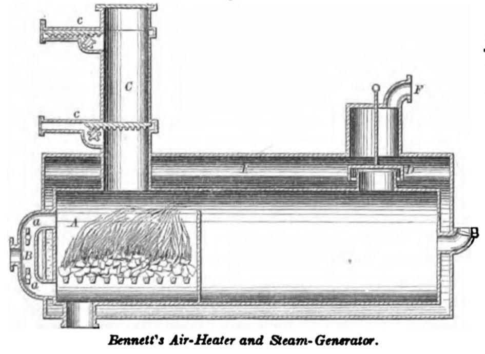
BENNETT, August 3, 1838. This is a combined air-heater and steam-generator, the combustion being maintained under pressure. The air is forced in by a pump, and enters above and below the grates in quantities regulated by the dampers a, a, in the branches of the pipe B. Coal is introduced through the charger C above, without allowing any notable amount of air to escape. The upper valve c being withdrawn, a charge of coal is dropped on to the lower valve, when the upper valve is shut, and the withdrawal of the lower one allows the coal to fall into the furnace A. The volatile products of combustion pass through the water-trap D, and mingle with the steam generated in the jacket E. The caloric current is purged of its grit and soot by the water in the trap D, and the combined heated air, gases, and steam pass by the pipe F to the engine. An equal pressure is maintained in the furnace and in the steam generating chamber.

WASHBURN, September 5, 1865. The water passes by pipe G to the coil B, where it is converted into steam which passes off by pipe C. Air from a force- pump enters the ash-pit A by the pipe if, and after supporting combustion in the furnace, the volatile portions pass off by the pipe D to the wash-box E, where the grit and soot are arrested. F is a water supply pipe and I a hand-hole for withdrawing accumulated matter arrested in the bath. After being deprived of impurities, the air passes by the pipe K, and joins the steam, the two passing by pipe L to the engine. The pressure through out the apparatus is equal, the air and water being forced into it at a pressure equal to that of the outgoing steam and air. The steam-generating tube B, being exposed to equal pressure within and without, may be of light material, and the hot-air current may vaporize a portion of the water in the cleanser E, which is also supplied under pressure. The strength is in the outer walls.

STILLMAN, August 9, 1864. The air-heating chamber is surrounded by a steam- generator, the steam from which is made the means, by injectors, of introducing the supply of air below the grate of the furnace, and also at a higher point, where it acts to assist the draft. For this purpose the steam in the generator is maintained at a higher temperature than the air in the furnace, and acts as a substitute for the air-pump in affording a supply of air for combustion of the fuel under pressure.
After the foregoing treatise on the early history of the air-engine and the consideration of the principles involved, the remainder of this article will be devoted to examples of the air-engines which have been introduced during the last twenty years. They are about eighty in number, and may be divided into five classes, in all of which the air is expanded by heat.
1st. Those in which the air is compressed into a reservoir, emitted in graduated amounts, heated, used effectively against a piston in a cylinder, and then discharged. This is the most numerous class. Some of them pass their air-supply through the furnace, and in others it is only heated by the furnace. In the former the discharge of the air is a necessity, not so in the latter; this brings us to the
2d. Those in which the air or gas is not expended, but the same air is caused to return to the heater and be again expanded and utilized. This is the subject of the English patent of Glazebrook, 1801, and Laubereau, 1859; and the United States patent of the latter dated 1849.
3d. Those engines in which the air or gas is not expended, but occupies two reservoirs communicating with the cylinder on the respective sides of the piston; the air in said reservoir being alternately heated and cooled to change its expansive force and thus reciprocate the piston. This was the form of Brunel’s engine, British, 1804; and Stirling’s, British, 1827; and Peters’s, 1882.
4th. Those engines in which water or steam is mingled with the air to moisten it and keep the working parts from abrasion; in some cases being introduced in quantity to be positively co-operative. These are AERO-STEAM ENGINES.
5th. Those engines in which the power derived is transferred to a body of water, to prevent burning the working parts and to obviate the necessity for air-tight joints.
It will be apparent that only a few representative examples can be shown within the limits assignable to this subject, in which, as is commonly the case, some inventors have numerous patents embracing details of construction, as the working of their engines developed defects and elicited remedies.
The first class of air engines
The first class is after the similitude of the Glazebrook, 1797, and Lilley, 1819.
Ericsson patented improvements in air-engines in 1851, 1855, 1856, 1858, and 1860. The following affords an example of one of his engines.
ERICSSON, specification patent of July 31, 1855, describes the invention substantially as follows (the illustration is reduced, from the official drawing, for this work):

- b, is the working-piston;
- c, the supply-piston;
- f, the exhaust-port;
- e, the induction-port.
- The regenerator consists of tubes k;
- m are the heater-tubes.
By means of a hand air-pump, applied to some part of the regenerator, a supply of atmospheric air is introduced at about the pressure of the atmosphere, and then the engine is in a condition to begin its operation.
Starting with the pistons of one engine in the position represented in the lower view, at the extremity of their outward stroke, as the crank s, moving in an upward direction is making that part of its circuit near the outer dead-point, and therefore imparting but little motion to the working-piston b, the supply-piston c is carried from the working piston and towards the head of the cylinder with a rapid motion by the action of the cam on the roller of the arm g, the cam rotating in the direction aforesaid, and its acting face being formed as represented, that the piston may be gradually started, rapidly accelerated, and, near the end, gradually arrested, and there retained in a state of rest as the extremity of the cam passes the roller.
During this inward motion of the supply-piston, the working-piston will be opened by the pressure of the atmosphere, to permit cold air to enter and fill that part of the cylinder between the two pistons. So soon as the supply-piston stops, the exhaust-port closes, and the continued inward motion of the working-piston begins to compress the cold air thus supplied, which of course closes the self-acting valve d, through which the supply was admitted by atmospheric pressure.
Thus supplied, cold air continues to be compressed by the working-piston, until the end of its inward stroke; and, as the power for effecting this compression is derived for the time being from the other engine, it is important to observe the condition of the connections. At the time the supply-piston of one engine is started and the air is entering by atmospheric pressure, and when the arm o, on rock-shaft p, with which the working-piston is connected by the rod n, is at its greatest leverage, the corresponding arm of the rock-shaft of the opposite engine is at its shortest leverage, but is moved inwards, and the supply-air, by reason of being gradually compressed, increases the resistance, the arm o gradually shortens in leverage, and the same arm of the opposite engine gradually, and in nearly the same ratio, increases in leverage, on the principle of the bent lever; thus applying the power required to compress the supply air to the best advantage.
It should be borne in mind, however, that the power thus applied to compress the supply-air is not actually expended, but merely borrowed; for it is so much added to the elastic force of the air by which, when heated, the engine is impelled.
Just before the supply-piston begins the inward stroke, just described, the education-valve g is opened, the induction-valve h having been previously closed so that the charge of the heated air, by which the previous stroke of the engine was effected, is permitted to escape freely into the atmosphere, so that the power required to move the supply-piston inward is very slight, the air escaping freely to the atmosphere on one side, and entering by atmospheric pressure on the other, through the valve d; but as the heated air exhausts or escapes front the cylinder, it passes around and among the series of small tubes k, of the regenerator, thus imparting its heat through the metal of the tubes to the cold air contained inside of the tubes, which air is thus partially heated preparatory to being finally heated in passing through the heater-tubes.
In this way much of the heat which would be otherwise wasted is saved. The supply of cold air having been introduced and compressed, the engine is prepared to be impelled by the expansive force of the heated air.
The education-valve g, having been closed during the greater part of the inward motion of the working-piston, the induction-valve h is now opened, which admits the heated air from the heater of the cylinder by which the supply-piston is forced outwards towards the working-piston.
The form of the fall of the cam 1 is such as to cause the piston to be carried back with a rapid accelerated motion, until it cornea nearly in contact with the working-piston; and, at first, in this outward motion of the supply-piston, the already compressed supply-air between the two pistons is still further compressed, not by the power of the engine, but by the elastic force of the heated air, the supply-piston being as it were suspended between the heated air from the heater on one side and the cold air of the other, with the self-acting valve r (in the side of the cylinder) interposed between the two; for it must be remembered that, as the heater and regenerator are in communication, the air, which is a perfectly elastic fluid, will be under equal pressure in both, notwithstanding a portion is more highly heated than the other; and, as the supply-air in the cylinder is simply separated from the air in the regenerator by the interposed valve r, in the side of the cylinder, the supply-piston will be moved outwards by the heated air, until the supply-air is compressed to an equal tension, and then the further motion of the supply-piston, effected by the cam l as it approaches the working- piston, will transfer the supply-air from the cylinder to the regenerator, through valve r.
The only power expended by the engine in this transfer will be the small amount required to move the supply-piston, between two equal pressures, to give the slight preponderance to the one necessary to open the valve r, through which the transfer is made. The moment the supply-piston passes this valve and overtakes the working-piston, the preponderance of pressure ceases, and the valve closes by gravity.
The specification states:
I claim the method of supplying fresh air to the engine, compressing and transferring it to the regenerator and heater, or either, by the action of the supply and working pistons within the one cylinder, operating on the principle and in the manner substantially as described, whereby the air is admitted, under atmospheric pressure, as the supply-piston is moving from the working-piston, as the previous charge of heated air is exhausting; so that the said supply-piston moves in equilibrio, or nearly so, and by which also the supply-air is finally compressed and then transferred to the regenerator and heater, or either, as the supply-piston moves between the supply-air and heated air, during the periods of the nearly stationary position of the working-piston.
I also claim, in combination with the double-piston movement of each cylinder, the methods of connecting the working-pistons of two single-acting engines to constitute a double-acting engine, b means of two sets of vibratory arms attached to each other, and vibrating on a common center connected with the two working-pistons, and with the two cranks on opposite sides of the crank-shaft, the two sets of arms acting on the principle of the bent-lever, and the crank-shaft being so located relatively to the cylinders and the centers of vibration of the arms, substantially as described, that the working-piston shall be at the end of its inward stroke at the time the crank is passing the dead point farthest from the point of connection of the connecting-rods with the vibrating-arm, as described, by which the power of that working-piston which is being impelled by the heated air is applied to the best advantage to operate the other working-piston during its return-stroke, and by which also the working- piston remains nearly at rest during the time the supply-piston is making that part of its outward stroke, during which the partially compressed air is finally and fully compressed and transferred to the regenerator and heater, or either, as described.
Since the experiments on a large scale, a smaller size of the Ericsson engine has been made efficient.
An Englishman, who was deputed to examine the engine, made a published report in which the following is found:
They all gave complete satisfaction and apparently ample power for the purposes to which they were applied; but without experiment it is impossible to say what quantity of power they actually furnish respectively, but, judging by the appearance of things, they all worked well and with surprising regularity, evidently developing a much larger amount of power from a given quantity of coal than could be obtained from steam-engines, as at present constructed, of corresponding powers. And being such that they may be placed an any location from which a chimney may be reached, and not requiring water or skilled attendance, they are particularly desirable as a driving power for small manufacturers, who are thereby enabled to conduct their operations in the business parts of the cities, by occupying upper lofts.
No attention is required for them while running, beyond what as necessary to throw in a few coals occasionally, which is all that is required to keep up a constant and uniform motion, –which considerations become of importance to those who require a small power only.
As to the appreciation of this machine by the public, it may well be said that whereas it was a few years ago looked upon as a mere mechanical curiosity, it is now regarded and acknowledged as a. reliable motive power.
The “London Engineer” adds:
That it is possible to construct an air-engine which will burn less coal than an average steam engine has been almost proved, but it is wrong to argue from this that the steam-engine is ‘used up.’ Something more is wanted than economy of fuel. We need permanence, absence of wear and tear, compactness, simplicity, and safety.
In every one of these points, except perhaps the last, hot-air engines cannot bear a moment’s comparison with the steam-engine. No large hot-air engines have ever been constructed and worked with success. The rubbing surfaces must be huge, and an efficient lubrication becomes an impossibility, hence friction is enormous. The dimensions of the working parts must be very great, or the temperature of the air very high. Surfaces nearly red hot cut into each other, and friction runs away with the power of the machine, the destruction of which is imminent each day.
Considerable improvements may be effected in lubrication, but experience with the steam-engine conclusively proves that the limit of temperature consistent with practical working is very soon passed. It is not safe to use superheated steam much hotter than 280 degrees, the cast-iron of the cylinders and valve faces becoming disintegrated and spoiled at higher temperatures. If air of no greater temperature is used, we have an effective pressure of not more than 7 lbs., or thereabouts, per square inch.
Marine engines with cylinders of 100 inches in diameter must be replaced under such a condition with others of 15 feet or 16 feet in diameter. Then would come huge air-pumps and regenerators. The machinery would take up as much space as boilers and steam-engines together; and all this to save perhaps a quarter of a pound of cola per horse per hour.
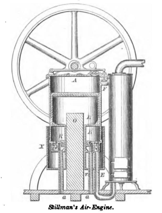
STILLMAN, June 26, 1860. The air is compressed and worked in a single cylinder by a single piston. The air is compressed in the space below the piston B, passes by pipe E to the heater, and thence by valve F to the effective space A above the piston. As the piston rises, air is drawn in between the hollow piston-rod B’ and the plunger O, cooling the former, and is ejected again as the piston descends. The induction-air enters at pipes aa, as the piston rises, the annular valve R being raised by the friction of its stuffing-box upon the hollow piston rod B’. The cylindrical chamber X is attached to the piston-rod B’, and rises and falls therewith so as to alternately draw and expel air through the annular space between it and the cylinder, for the purpose of cooling the latter.

ROPER, June 9, 1863. The furnace is lined with fire-brick on all sides except the bottom. The air is condensed in the pump above and passes down by the pipe Z, being admitted above or below the grate in quantities proportioned to the requirements of the fuel. The air passes from the furnace A by an opening d, and is admitted, on the rising of valve a, to the space H, when it is rendered effective against the piston B. The exhaust valve b is raised to allow the descent of the piston, the valve being automatically worked by the usual means, and the cut-off being adjustable as required.

BALDWIN February 14, 1865. In this engine the air is driven out of the force-pump A by the descent of the piston B, which is connected by pitman C with the crank D. The air from the pump A passes, by passages H, to the tuyeres I around the furnace J, into which it issues by a series of openings on the inner faces of the annular tuyeres. These air-passage rings are interchangeable with the movable rings which form the lining of the furnace. The air passes from the primary to a secondary furnace, and thence by passages and valve-ways to the working-cylinder M, where it acts upon the piston F to raise the walking-beam E, and the latter connects by pitman G with the crank D.
The disk-valves are made of flexible material, and are guided by marginal, vertical pins, which form a cage to restrain the disks from lateral movement, but permit free, vertical play. The air, after expanding in the working-cylinder, becomes sensibly colder and is exhausted into the atmosphere. A connecting-rod eccentrically journaled to the main- shaft operates toes which trip the inlet and exhaust-valves of the working-cylinder.
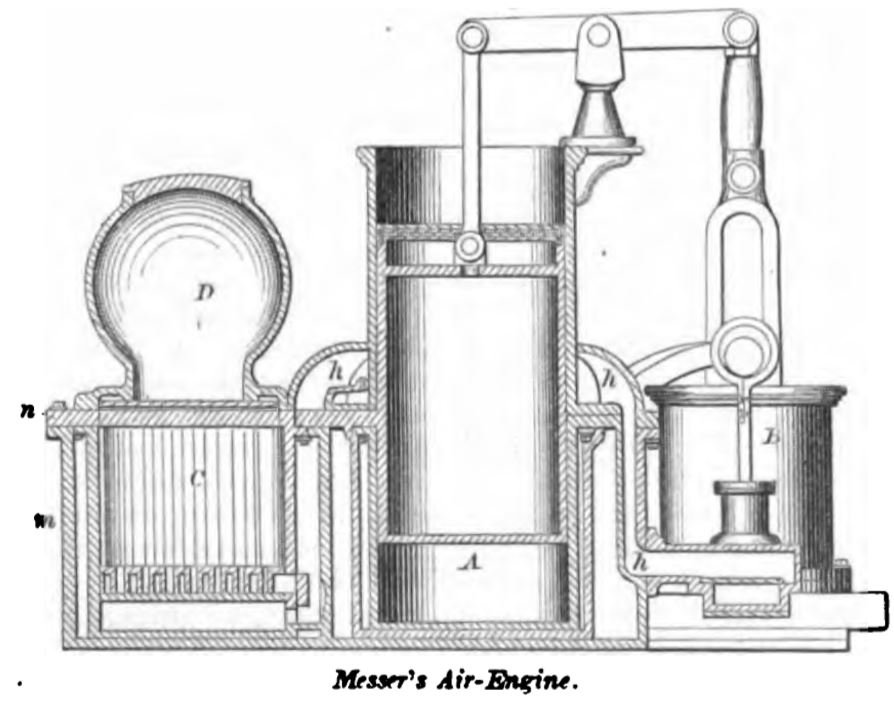
MESSER, March 7, 1865. The cylinder A, air- pump B, and furnace C are on a plane, and the feed- box D over the latter. The packed portion of the piston works in the upper part of the cylinder, which is cooled by air in the passage h, leading from the air-pump to the furnace. A check-valve in the passage prevents the reflux of air. The foundation plate of the engine has high sides m, and forms a water-reservoir in which steam is generated by radiation from the furnace-walls. A top-plate n forms the top of the reservoir, and the cylinder is protected by a double wall which prevents immoderate subtraction of heat therefrom. Air from the pump circulates through the hollow grate-bars. A pump is provided for injecting combustible fluid, to mix with the solid fuel in the furnace, and all the volatile products of combustion are passed through the working-cylinder, the induction and education valves being worked in the usual manner.
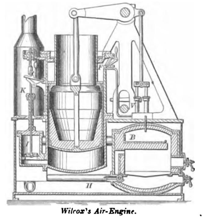
WILCOX, May 16, 1865. This engine is substantially on the principle of the engine of Sir George Cayleys (about 1830). The fire is fed with air, under pressure of a pump, and the volatile products of combustion are passed through the working-cylinder.
With each descent of the piston air is drawn through the inhaling valve F, and fills the space above the piston. On the ascent of the valve the air is driven through the regenerator, and becomes partially heated by contact with the ducts carrying out heated exhaust-air. It thence passes by pipe H to the furnace, a part entering above and a part below the grate as regulated by the faucet-valve. This valve is worked automatically by a thermostatic arrangement, so that when the fire becomes unduly heated the supply driven through the fuel is decreased and combustion checked.
The compressed and heated air thence passes, by pipe B, to the valve-chest I. The raising of the valve admits air to the effective space below the piston, and closes by the tripping of the adjustable cut-off arrangement; this is effected late or early in the stroke, as may be required.
The doors of the furnace and ash-pit are secured by cramps and hollow bolts to the walls, and are removable to replenish the fuel, or for grinding or packing to make an air-tight joint.
The second class of air engines
The second class is as the principle of the English patents of Glazebrook, 1797; and Parkinson and Crosley, 1827.
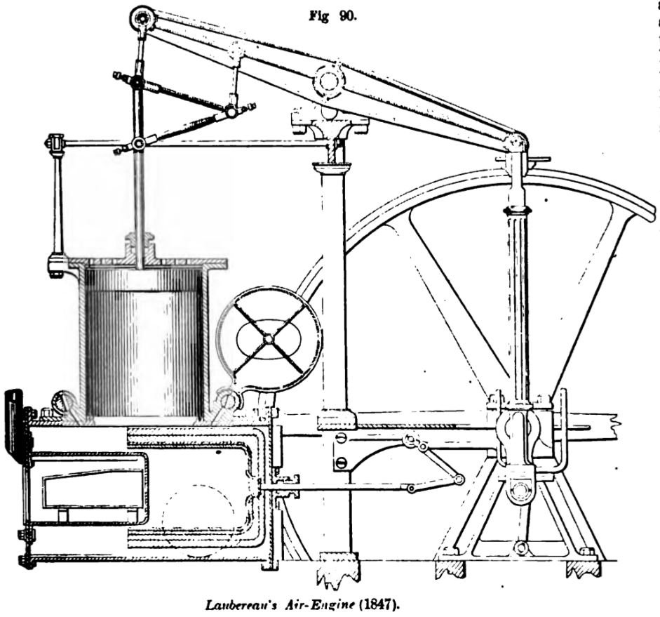
LAUBEREAU, April 10, 1849; patented in England, 1847. This engine is the first which embodies the peculiar features of a furnace in the air-heating chamber, and a hollow plunger of corresponding form.
The air is alternately dilated and contracted by absorbing and giving out caloric, the air when separated by heat forcing up a piston in a cylinder, which is in turn forced down by the pressure of the atmosphere when the air is condensed by the abstraction of heat, the air for the alternate dilatation and contraction being carried over a heating and cooling surface by the motion of a plunger in a cylinder that communicates with the cylinder of the engine.
The plunger is made hollow, with its external and internal surfaces made of some good conductor of caloric separated by a non-conductor, the said plunger being adapted to move within a surrounding cooling-vessel and so combined with a heating-vessel made of some good conductor of caloric, and heated by the application of heat internally, that the said hollow plunger shall alternately cover and uncover it, and thus cause the contained air alternately to pass over the heated surfaces to dilate it, and then over the cold surfaces to contract it, the said surrounding vessel being in connection with a cylinder to which is adapted a working-piston.
The operation is as follows: before heat is applied, air is admitted, under the pressure of the atmosphere, through one of the valves or cocks; fire is then made in the furnace until the contained air is dilated; a portion of which is then permitted to escape through one of the valves or cocks, which is then closed. The heat is then continued until the air has acquired sufficient elasticity to force up the piston. This communicates motion to the crank-shaft, and toward the end of the upward motion of the piston, the cam on the main shaft moves the plunger until it covers the heater, and this motion of the plunger causes the air contained between it to pass between its outer surface and the inner surface of the surrounding vessel, and to accumulate at the back end of the plunger, so that, the heat being entirely shut in, the air is cooled by contact with the cold surface of the surrounding case and outer surface of the plunger, the air thus contracted producing a partial vacuum which permits the piston to be forced down by the pressure of the atmosphere above. As the piston approaches the end of its downward stroke, the cam moves back the plunger, which transfers the cold air from the outside to the inside, thus causing it to pass in a thin film over the surface of the heater and the inner and heated surface of the plunger. It is thus again dilated, that by its elasticity it may again force up the piston.
In this way each stroke of the plunger causes the air to pass over the heated surfaces to dilate it, and then over the cold surfaces to condense it. The plunger also has the effect to shut in the heat of the heater, receiving heat therefrom in the meantime while its external surface is kept cold by the surrounding case, the non-conductor interposed between them preventing the heat of the internal surface from being transmitted to the external surface.
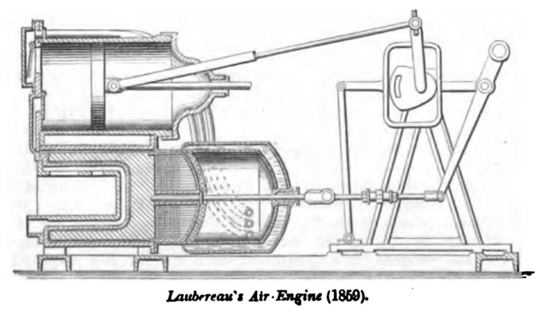
This engine has been since modified (Patent in England, July 22, 1859) by the introduction of a valve in the passage between the heater and working-cylinder, and at the education from thence into the pipes which conduct the air back from the working-cylinder to the cool end of the chamber.
This air-engine is said to be coming into great favor on the continent of Europe and in the later form is very compact. The operation of the engine is so similar to the preceding that it does not call for a lengthy description. The jacket around the cool end of the air-chamber has a current of water, or sonic other means of refrigeration, so as to render it more prompt and effective in its action on the air. The working-cylinder is connected alternately to the respective ends of the chamber below, by passages whose valves open and close, according to the direction of the current.
SCHWARTZ, December 20, 1864. This invention is thus described officially:
The object of this invention is to produce an air-engine to work upon the recuperative system, and thus to use the same air over and over. Its novelty consists, first, in the generator, which is composed of a strong flat-aided vessel, with rounded neck at the top, which is suspended over the fire in the furnace. From the bottom of this generator protrude downwards several bottle-shaped tubes which are open towards the inside space of the generator.
This generator is filled with a liquid whose boiling-point is very high, say from 500° to 700°. The air heated in the generator passes through a pipe to the cylinder, which constitutes the second novel feature of the engine, and is composed of three distinct parts, the central one of which is the working cylinder, the end ones being filled with small tubes, into which rods are fastened to the piston-neck for the purpose of agitating the entire body of air during the process of expansion.
The third feature of novelty consists in passing the gas, after it has expended its force upon the piston, through the generator, which is constructed rectangularly, and has a dividing plate in its center. This vessel is filled with horizontal tubes, which are closed at both ends, and are partially filled with a fluid which is designed to extract the heat from the air or gas as it passes from the engine, and transmits it to the air which is passing to the opposite side of the piston.
The third class of air engines
The third class is on the principle of the Stirling engine, described in a preceding portion of this article.
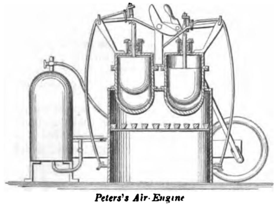
PETERS, November 18, 1862. The air is heated in two vessels connected with two opposite ends of the working-cylinder, and the invention consists in so operating the two plungers that the one in either heating-vessel is stationary in its uppermost position, with the space below it full of heated air, while the working-piston is making the stroke from the end of the cylinder in connection with that vessel, the plunger in the other heating vessel making both its upward and downward stroke in the meantime, and causing the latter vessel to be filled with heated air to produce the return stroke of the working piston. The gland which is used to compress the packing in the stuffing-box is made with a deep cup in its upper part for the reception of oil, and around the upper edge of this cup is secured a leather collar in close contact with the plunger-rod, so as to prevent the escape of air.
The engine of NAPIER AND RANKINE, patented in the United States, September 19, 1854, and in England June 9, 1853, is of this class.
The fourth class of air engines
The fourth class includes those which use steam to lubricate the parts; an example will be given, but it is not to be inferred that it is confined to one. The immense expenditure of grease has induced the use, in many or perhaps most of the air-engines, of moistened air as suggested by Glazebrook 1797, Oliver Evans about the same time, and by Bennet 1838.
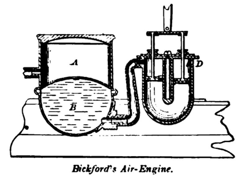
BICKFORD, June 6, 1865. The air is compressed in the reservoir by an annular piston; entering at; the valve D during the down stroke, and passing through the piston during the up stroke. It moistened by passing through a body of water B before reaching the compressed-air reservoir A.
The fifth of air engines
Of the fifth class is the patent of SHEARER, September 3, 1861; in which two cylinders are used with two pistons, the faces of which are in contact with water, which is caused to pulsate by the action of bodies of air. The air is acted upon alternately by heating and refrigerating means.
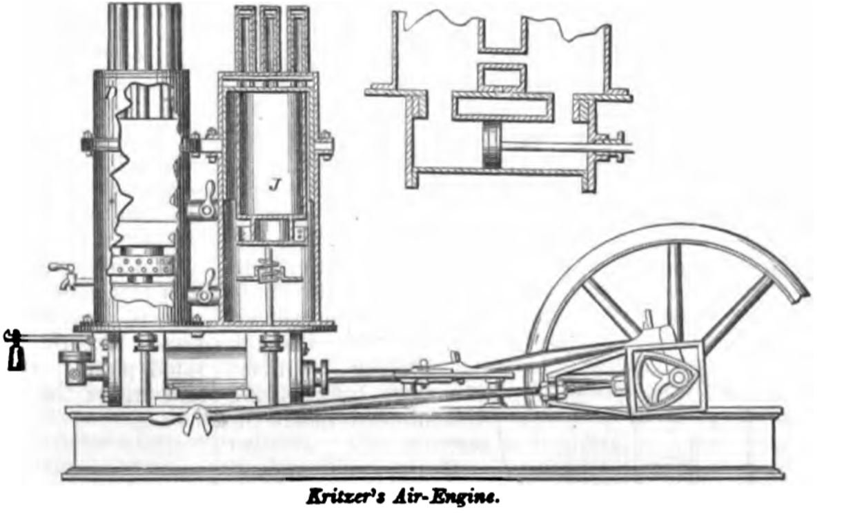
KRITZER, July 29, 1862. This invention also belongs to the fifth class.
The working-cylinder, shown in longitudinal section, is filled with water, which also extends into the lower portion of each of the vertical cylinders above. The lower portion of each upper cylinder forms an air-condensing space. The spaces D, above the pistons J, are the air-heating spaces where it is made effective. To the bottom of each piston is attached a sprinkling-trough of light metal, with perforated sides, so that at each descent of the piston it will be filled with water, and as it rises will distribute the same upon the inside of the cylinder.