Patent of Ericsson's 1851 Caloric Engine
Source : United States Patent Office
Title: Improvement in Air-Engines
Inventor : John Ericsson, of the city, county, and State of New York
Date: Patented Nov. 4th, 1851
Patent #: US8481
To all whom it may concern:
Be it known that, I JOHN ERICSSON, of the city, county, and State of New York, have invented a new and improved engine for producing motive power by the dilation or expansion of certain gases or fluids by the application of caloric; and I do hereby declare that the following is a full, clear, and exact description thereof, reference being had to the accompanying drawings, making part of this specification.
My invention consists in certain improvements in the known principle of producing motive power by the application of caloric to atmospheric air or other permanent gases or fluids susceptible of considerable expansion by increase of temperature, the mode of applying the caloric being such that after having caused the expansion or dilatation which produces the motive power the caloric is transferred to certain metallic substances, and again retransferred from these substances to the acting medium at certain intervals or at each successive stroke of the motive engine, the principle supply of caloric being thereby rendered independent of combustion or consumption of fuel.
Accordingly, while in the steam-engine the caloric is constantly wasted by being passed into the condenser or by being carried off into the atmosphere, the caloric is in such engines employed over and over again, dispensing with the employment of combustibles, excepting for the purpose of restoring the heat lost by the expansion of the acting medium and that lost by radiation; also for the purpose of making good the small deficiency unavoidable in the transfer and retransfer of the caloric.
Having thus stated the object and general character, I will now proceed to describe the structure of my improved engine for producing motive power, reference being had to the drawings.
Description of the Caloric Engine
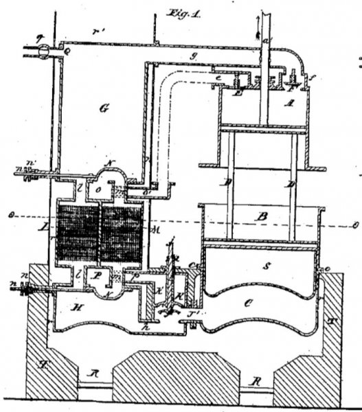
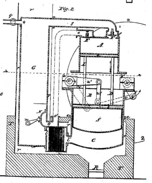
Figures 1 and 2 represent longitudinal sections of my engine, both being alike in all essential parts, differing only in part of the detail, as will be clearly seen by the following description.
I will first describe Fig. 1

A and B are two cylinders of unequal diameter, accurately bored, and provided with pistons a and b, the latter having air-tight metallic packing-rings inserted at their circumferences. I call A the “supply-cylinder” and B the “working-cylinder.”
a' is a piston-rod attached to the piston a, working through a stuffing-box in the cover of the supply-cylinder.
C is a cylinder wit a concave or convex bottom attached to the working-cylinder at cc. I shall this vessel the “expansion heater.”
D D are rods or braces connecting together the supply-piston a’ and the working piston b.
E is a self-acting valve opening inward to the supply-cylinder; F, a similar valve opening outward from said cylinder and contained within the valve-box f; G, a cylindrical vessel, which I call the “receiver,” connected to the valve-box f by means of the pipe g.
H is a cylindrical vessel with an inverted spherical bottom. I call this vessel the “heater.”
J is a conical valve supported by the valve-stem j and contained in the valve-chamber J’, which chamber also forms a communication between the expansion heater C and heater H by means of the passage h.
K is another conical valve supported by the hollow valve-stem k and contained within the valve-chamber k’.
L and M are two vessels of cubical form, filled to their utmost capacity, excepting small spaces at top and bottom, with disks of wire-net, or straight wires closely packed, or with other small metallic substances or mineral substances, such as asbestos, so arranged as to have minute channels running up and down. I call these vessels L and M with their contents “regenerators.”
L l m m are pipes forming a direct communication between the receiver G and the heater H through the regenerators.
N N are two ordinary side-valve arranged to form alternate communications between the pipes l l and m m and the exhaust chambers O and P, on the principle of the valves of ordinary high-pressure steam-engines, by means of valve-stems n n working through stuffing boxes n’ n’.
P is a pipe communicating between the valve-chamber k’ and exhaust-chamber P; o’, pipe leading from exhaust-chamber O.
Q is a pipe leading into the receiver G, provided with a stop-cock q; R R, fire-places for heating the vessels H and C; r r r r, flues leading from said fire-places and terminating at r’.
S is a cylindrical vessel attached to the working-piston b, having a bottom corresponding to the expansion-vessel C. This vessel S, which I call the “heat-intercepting vessel,” is to be filled with fire-clay at the bottom and ashes, charcoal, or other non-conducting substance toward the top, its object being to prevent the intense radiating heat of the furnace from reaching the working-piston and cylinder.
T T represent brick-work or other fire-proof material surrounding the fire-places and heaters.
I now proceed to describe Fig 2. All corresponding parts in this figure are marked by similar letters of reference as in Fig 1. It will, however, be well briefly to repeat the description of the same.

A is a supply-cylinder; a, supply-piston; B, working-cylinder; b, working-piston; C, expansion heater; c c, junction of working-cylinder and expansion heater; D, rods connecting the supply and working pistons; E, inlet-valve of supply-cylinder; e, valve-chamber of the same; F, outlet-valve of supply cylinder, and f its chamber; G, receiver; g, pipe connecting the same to outlet-valve chamber f; L, regenerator; l, passage between the same and the receiver; l’, passage between the regenerator and the expansion heater; N’, slide-valve; n, stem or spindle for working the same; O, exhaust-chamber under the slide-valve; o’, outlet-pipe; Q, pipe leading into receiver; q, stop-cock in the same; R, fire-place; r r r r, flues leading from said fire-place r’, exit of said flues; T, brick-work surrounding the fire-place and flues; U rock-shaft, supported at both ends by appropriate pillow-blocks u u; u’, crank lever or arm attached to said rock-shaft; u’’, link connecting said arm to the working-piston b; V, another crank lever or arm attached to the extreme end of the rock-shaft; X, crank shaft or axle, having a crank Y firmly attached; v, connecting-rod connecting the arm V to the crank-pin y of the crank Y; y’ y’, pillow-blocks supporting the crank-shaft X.
Z Z represent the circumference of a fly-wheel, paddle-wheel, propeller, or other rotary instrument to be worked by the engine.
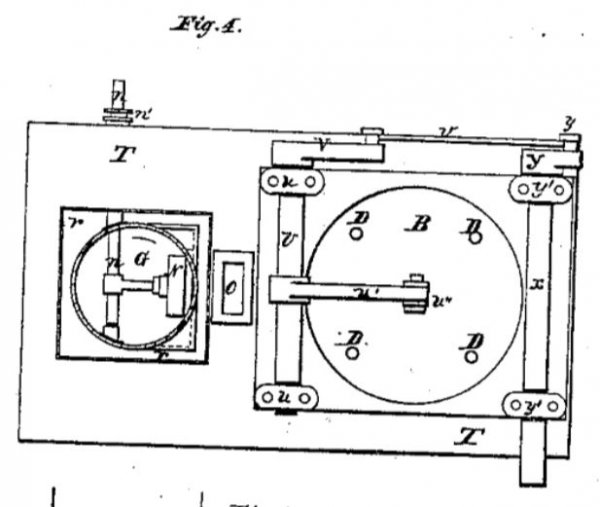
Fig. 3 represents a top view of Fig. 1, and Fig. 4 a top view of Fig. 2.


Operation of the Caloric Engine
Before describing the operation of my improved engine it will be proper to observe that the piston-rod a’ only receives and transmits the differential force of the piston b - viz., the excess of its acting force over the reacting force of piston a. It will also be proper to observe that this differential force imparted to said piston-rod may be communicated to machinery by any of the ordinary means, such as links, connecting rods, and cranks, or it may be transmitted directly for such purposes as pumping or blowing.
I have further to observe that the conical valves K and J may be worked by any of the ordinary means, such as eccentrics or cams, provided the means adopted be so arranged that the valve K will commence to open the instant the piston b arrives at the full upstroke, and be again closed the instant that the piston arrives at the full downstroke, while the valve J is made to open at the same moment and to close shortly before or at the termination of the upstroke.
In like manner the slide-valve M’ is to open and close as the piston b arrives, respectively, at its up and down stroke, similar to the slide-valve of an ordinary high-pressure engine. It will be seen that the link u’’, like the piston-rod a’, only transmits the differential or useful force of the piston b.
Having thus described the construction of my engine, I will now proceed to describe the manner in which the same is to be put into operation, reference being first had to Fig. 1.
Before starting fuel is put into the fire-places R R and ignited, a slow combustion being kept up until the heaters and lower parts of the regenerators shall have been brought to a temperature of about 500°. By means of a hand-pump or other similar means atmospheric air is then to be forced into the receiver air is then to be forced into the receiver G through the pipe Q until there is an internal pressure of some eight or ten pounds to the square inch. The valve J is then to be opened, as shown in the drawings.
The pressure entering under the piston b will cause the same to move upward, and the air contained in A will be forced through the Valve F into the receiver. The slide-valves N N being by means of the two stems n n previously so placed that the passage l l are open, the air from the receiver will pass through the wires in L into the heater H, and farther into C, the temperature of the air augmenting and the quantity increasing as it passes through the heated wires and heaters. The smaller volume forced from A will by expansion suffice to fill the larger space in C.
Before the piston arrives at the top stroke the valve J will be closed, and at the termination of the stroke the valve K will be opened. The pressure from below being thus removed the piston will descend and the heated air in C will pass through k’, p, P, and m into the regenerator M, and in its passage through the numerous small spaces or cells formed between the wires part with the caloric, gradually falling in temperature until it passes of at o’, nearly deprived of all its caloric.
The commencement of the descent of the piston a will cause the valve F to close and the valve E to open, by which a fresh charge of atmospheric air is taken into the cylinder A. At the termination of the full downstroke the valve K is closed and the valve J again opened, and thus a continued reciprocating motion is kept up.
It will be evident that after a certain number of strokes the temperature of the wires or other matter contained in the regenerators will change. That of M will become gradually increased and that of L diminished. The pistons of the slide-valves N N should therefore be reversed at the termination of every fifty strokes of the engine, more or less, which may be effected either by hand or by a suitable connection to the engine.
The position being by either of these means accordingly reversed to that represented in the drawings, the heated air or other medium passing off from C will now pass through the partially cooled wires in L, while the cold medium from the receiver will pass through the heated wires of M, and on entering H will have attained nearly the desired working temperature.
In this manner the regenerators will alternately take up and give out caloric, whereby the circulating medium will principally become heated independently of any combustion after the engine shall have been once put in motion.
The role of the Regenerator
Having thus with special reference to Fig. 1 described the manner of putting my improved engine into operation, I have now to notice that my said engine, as represented in Fig. 2, is operated precisely in the same manner, excepting that the regenerator is arranged in a single vessel, and that the metallic substances contained therein take up the caloric from the circulating medium that leaves the working cylinder or vessel C and returns the same to the circulating medium that enters at each stroke of the engine, instead of transferring and retransferring the caloric at intervals, as shown in Fig. 1.
The manner in which the differential or useful upward force of the working piston b, Fig. 2, in conjunction with its descending power caused by gravity, is made to impart rotary movement to the crank-shaft X becomes self-evident on examining the disposition of the working-gear of the engine, as shown in the drawings.
It is particularly worthy of notice that the relative diameter of the supply and working cylinder will depend upon the expansibility of the acting medium employed. Thus in using atmospheric air or other permanent gases the difference of the area of the pistons may be nearly as two to one, while in using fluids— such as oils— which dilate but slightly the difference of area should not much exceed one-tenth.
I have next to notice that in employing any other medium than atmospheric air it becomes indispensable to connect the outlet pipe o’ and the valve-box e of the inlet-valve E, as indicated by dotted lines in both figures, these dotted lines representing the requisite connecting-pipe. The escaping air or fluid at o’ will, when such a connecting-pipe has been applied, furnish the supply-cylinder independently of other external communication, and the acting medium will perform a continuous circuit through the machine under this arrangement, the operation being in other respects as before described.
It is evident that the several parts composing my improved engine may be arranged in various ways, and that the external form thereof may be greatly changed, while its principle of operation remains substantially as I have ascertained and described.
Claims
What I claim as my invention, and desire to secure by Letters Patent, is:
-
The working cylinder and piston and the supply cylinder and piston of less piston-surface, the two pistons being connecting with each other and working together, substantially as specified, in combination with the regenerator and heater, so that the air or other circulating medium shall pass from the supply-cylinder to the working cylinder through the regenerator, substantially as specified, and give motion to the engine through the difference of area of the pistons, and this I claim whether the air or other circulating medium be made to pass on the return stroke from the regenerator to the supply cylinder or any other receiver or into the atmosphere.
-
In connection with the working-cylinder, the employment of two regenerators, substantially as specified, in combination with the valves or their equivalents, for the purpose of causing the air or other circulating medium to pass during a series of strokes through one of the regenerators to the working-cylinder and back from the working-cylinder through the other regenerator, and then reversing the action, substantially as specified.
-
Interposing the heater between the regenerator and the working-cylinder, substantially as specified, to heat the air or other circulating medium as it passes form the regenerator to the working-cylinder, as specified, to supply the heat required.
- Communicating the power of the engine to the working-beam or its equivalent by the attachment thereof to one of the pistons or piston-rods between the open ends of the two cylinders, said pistons being connected or braced to each other, substantially as specified, whereby I am enabled to render the engine compact and effectually to brace and connect the two pistons and avoid undue strain, as specified.
J. ERICSSON
Witnesses:

C. AUSTEN BROWNE,
WM. H. BISHOP