The Stirling Engine of 1816
Source : The Engineer, Dec. 14, 1917, p. 516 - Part 1 - The Economiser
Date of patent : 1816
Patent #: 4081
Robert Stirling patent of 1816, which entire writing is given here after, has been published in extenso for the first time by the The Engineer of Dec. 1917 at the occasion of the centenary of the Stirling Engine.
All my improvements for diminishing the consumption of fuel consist of the different forms or modifications of a new method, contrivance, or mechanical arrangement for heating and cooling liquids, airs or gases, and other bodies by the use of which contrivance heat is a abstracted from one portion of such liquids, airs, and other bodies and communicated to another portion with very little loss; so that in all cases where a constant succession of heated liquids or other bodies is required, the quantity of fuel necessary to maintain or supply it is by this contrivance greatly diminished.
The first modification of said contrivance or arrangement is described as follows:
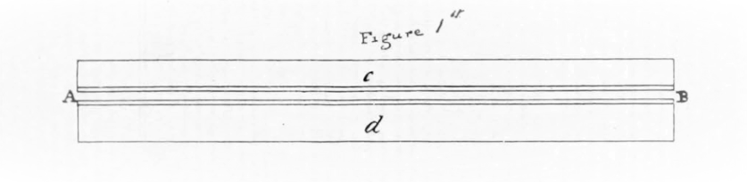
A.B. fig. 1 is a pipe, channel or passage, formed of metal, stone, bricks or other materials according to circumstances i.e. according to the chemical agencies of the bodies to be heated or cooled and the degree of heat in said bodies. The hot liquid, gas, or body to be cooled is by any means made to enter the passage at A and to pass along to its other extremity B.
In its progress it gives out its heat to the sides of the passage or to any bodies contained in it and issues at B at nearly the original temperature of the passage.
In this manner the extremity at A and a considerable portion of the passage is heated to nearly the temperature of the hot liquid while the extremity B still retains its original temperature nearly. When the temperature of the passage at B has been raised a few degrees the motion of the fluid from A to B is stopped and a portion of fluid which is required to be heated and which is supposed to be a few degrees colder than the extremity of the passage at B is made to traverse the same passage in a contrary direction i.e. from B to A; by which means it receives heat from the sides of the passage or other bodies contained in it and issues at A at early the same temperature with the fluid to be cooled. When the temperature of the passage at A has thus been lowered a few degrees, the process is again stopped and a portion of the fluid to be cooled is made to pass from A to B and so on alternately.

The second modification of any said contrivance or arrangement consists in interposing a thin plate of metal or other materials, according to circumstances, between two currents of liquid gas or vapour which are made to run in opposite directions.
A.B. fig. 2 represents such a plate and c.d., two passage between which it is interposed. The fluid to be cooled is made to traverse the passage d from A to B and the fluid to be heated is made to tranverse the passage d from B to A.
The extremity of the plate at A is kept hot by the current in d and the extremity B is kept cold by the current in c. The plate A.B. abstracts the heat from the fluid in the passage d and communicates it to that in c with very little loss.The waste or escape of heat from the passage is prevented by their being surrounded with charcoal powder, wood, bricks or any substance that does not easily permit heat to pass through it.
In the construction of the passage in both Modification of my contrivance for heating and cooling liquids and other bodies I observe the following rules:
-
When the passage are made of metal or any other substance that conducts or transmits heat easily I make the metal or other substance as thin as possible to prevent the heat from being transmitted in this manner from the hot to the cold extremity of the passage.
-
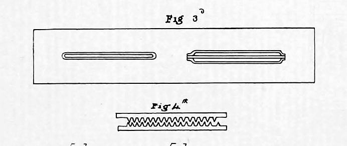
Liquids and airs being very imperfect conductors of heat I make the passages very narrow (at least in one direction) in proportion to their length, for the purpose of heating and cooling more completely the liquids or airs that pass through them. A transverse section of the passages is given at A, B and C fig. 3.
-
When the passage cannot be made sufficiently narrow I make their sides jagged or rough by bodies projecting form them as represented at fig 4 or I adopt any similar method for promoting the internal motions of the fluids and the ready communication of heat to them or to the passage.
- When the width of the passage cannot be sufficiently diminished increase its length in order to attain the same end. The form and construction of the tubes, passages and plates in both the modifications of my general contrivance or arrangement may be varied according to circumstances; but the benefit to be derived from this contrivance arises from the fluids and other bodies to be heated and those to be cooled being made to move in opposite directions and it is for the invention or improvement of this arrangement that I have applied for and obtained His Majesty’s Letter Patent.
In his patent Stirling describes the use of the regenerator (economiser) for an air engine but also for other applications like furnaces to the saving of fuel in breweries, distilleries, dye works and other manufactures.
Here we reproduce only the application to the hot air engine.
Having thus described and ascertained the nature of my Invention I shall now describe [...] my engine for moving machinery, and the following is a general description of the manner in which this is performed.
I employ the expansion and contraction (or either) of atmospheric air or any of the permanent gases by heat and cold to communicate motion to a piston or other similar contrivance.
In order to produce this expansion and contraction I cause the air to pass from a cold to a hot part of the engine and the contrary alternately either in the same passage in the manner described at the explanation of Fig. 1, or in different passages as described at fig. 2.
I apply fire to the warmest part of the engine, in order to supply the waste of heat occasioned by its transmission from the hot to the cold parts by the radiating and conducting power of the materials of which they are formed, by the change of capacity for heat which the air suffers from condensation and rarefaction, and by the impossibility of transferring the whole of the heat from the air to the passages and the contrary and I apply a stream of cold air or water to the coldest part of the engine to carry off said waste heat.
The passages are of course hot at the one extremity and cold at the other, and in passing through them the air is alternately heated and cooled or expanded and contracted.
The following is a particular description of that form of my engine which I consider as the best.
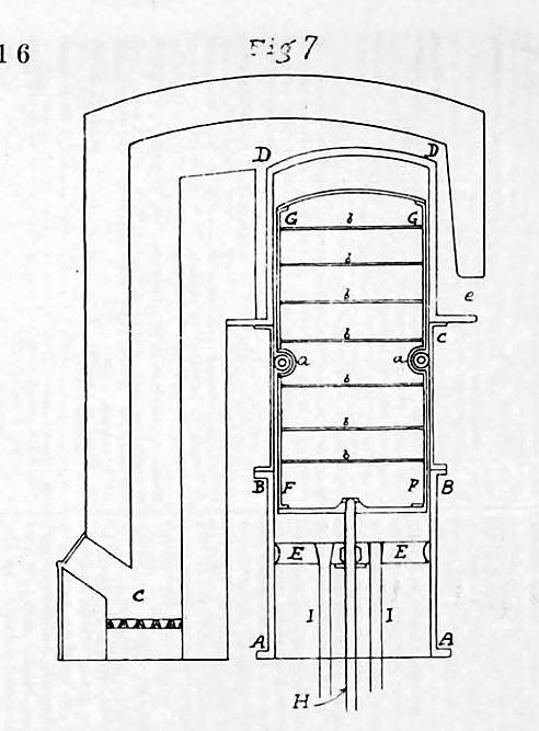
AADD Fig. 7 is a cylinder composed of three parts accurately joined together by rivets or screws and rendered airtight by hammering or soldering the joinings.
The part AB is formed of cast iron and accurately bored, the part BC is made of sheet or cast iron as thin as possible (as one tenth of an inch), and the part CD is of sheet or cast iron.
To this cylinder is fitted a piston EE which is made airtight in the usual way, and provided with rods II for communicating its motion.
FFGG is a hollow cylinder also as thin as possible made of sheet iron covered with thin plates of polished brass or silver to prevent the waste from radiation and divided into compartments by plates bb for the same purpose. It is shut on all sides and air tight, kept at a small distance from the outer cylinder by wheels aa, or any similar contrivance and furnished with a rod H working through a stuffing in the center of the piston, by means of which it is moved up and down.
This inner cylinder I call the plunger.
The part BD of the outer cylinder is kept hot by the flame or heated airs of a fire C applied at DD made to descend on all sides of the cylinder to C and allowed to escape at e.
The part AB is kept cool by a stream of air or of water directed upon it, and the part BC increases in temperature from B to C. The temperature of the plunger increases form F to G and the interval between the cylinder and plunger is partially filled with wires wound round the later and kept at a small distance from it and from one another by wires laid along it at right angels to the former, in order to heat and cool the air more completely.
This intervals is on each side about one fiftieth of the whole diameter of the cylinder. Figures 7 and 8 are drawn to a scale of one half inch to a foot except the thickness of the metal which is to no scale. The space contained by the cylinder and piston is filled with atmospheric air.
Figure 8 is an elevation of the engine.
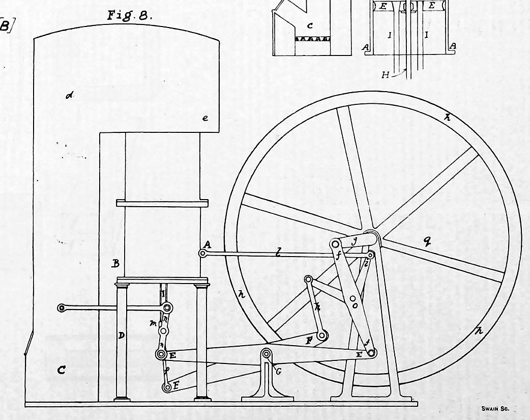
ABC the cylinder DD pillars supporting it, EE a beam centered at G to which the rods II of the piston are connected by a parallel joint NN: ff an arm which connects said beam to the crank g.
I o I a bent lever joined to said arm to o and connected to the fixed point A by the rod l, and to the other extremity of the beam FF by the rod k. This beam is also centered at G and moves between two plates or similar beams of which the beam EE is composed. P a rod by which FF is connected to the rod of the plunger M a slider upon the rods of the piston fixed to the rod of the plunger to render its motion steady and parallel.
hhh the fly upon the same axle with the crank.
cde the furnace and flues.
The Operation of the engine is explained as follows
The part of the cylinder surrounded by the flues is heated to a temperature of 480° F (249° C) higher than the part AB.
In the position represented at fig. 8 the plunger is in contact with the piston, by which means the included air is brought to the warm part of the cylinder has its elasticity increased and presses upon the piston with a force greater than that of the atmosphere.
The piston is thus forced downwards and the rod ff and the crank g upwards till the pressure of the included air and that of the atmosphere become equal.
The impulse communicated to the fly carries the end of the crank towards q, and the arm ff and bent lever ii are brought to such a position as to depress the rod k and thus to raise the plunger from the piston.
The included air is thus made to descend between the plunger and cylinder and brought to the cold part; it is cooled in its descent, has its elasticity diminished, and its pressure becomes less than that of the atmosphere, the piston is forced upwards, and the crank downwards.
The revolution of the fly and crank again bring the plunger towards the piston, the air ascends through the same passage by which it descended, is heated in its ascent and forces the piston downwards and the crank upwards, and so on alternately. In this manner a rotary motion is produced which may be applied to the moving of machinery.
The force of the engine is regulated by allowing a portion of air to escape outwards and inwards by a small cock which is opened and shut by a governor as in steam engines, and placed in the cold part of the cylinder immediately above the highest ascent of the piston.
The distance which the rod of the plunger H fig. 7 moves through the piston I call the stroke of the plunger and I make it equal to that of the piston when the difference of temperature in the hot and cold parts of the cylinder is 480° F (249° C). When the difference is less than 480° F (249° C) I make the stroke of the plunger proportionally greater than that of the piston, and the contrary when the difference is greater.
The length of the arms of the bent lever I o I and of the rod k which is necessary to make the plunger just touch the piston on the one hand and the upper end of the cylinder on the other determine by experiment as being the most convenient method known to me. I do not answer for the absolute correctness of those in the plan.
The cylinder is inverted to prevent the oil used to make the piston airtight from getting to the hot part and wasting the heat.
In the foregoing description, wherever I have specified more than one material or more than one method of performing the same thing, I have placed that first to which I give the preference; but I reserve to myself the power of using any materials and applying my new contrivance for heating and cooling bodies, to the purpose to which it is applicable in any form or manner which further experience may prove to be advantageous and which is not inconsistent with the terms of his Majesty’s Letter Patent.
In witness whereof I the said Robert Stirling have hereunto set my hand and seal this Twentieth day of January in the year of our Lord one thousand eight hundred and seventeen.
Signed sealed and delivered
In the presence of:
Rob. Cameron - Accountant in Edinburg
Francis F. Cameron - Preacher of the Gospel in Edinburg
Addendum

The engraving above shows the first Stirling engine, as specified in the 1816 patent, and built in 1818 for pumping water at an Ayrshire quarry.
The top of a long vertical cylinder A is heated by flue gases from furnace B; the bottom is cooled either with water or by atmospheric convection. The cylinder contains the dpluner (or displacer) C and the power piston D.
The plunger is of rather smaller diameter than the cylinder A and centered by small rollers.
As the plunger moves up and down, air is pushed from the hot space F (above the plunger) via an economiser (or regenaretor) into cold space E located between the bottom of the plunger and the top of the piston. Then the air goes back again.
The economiser (not shown in the engraving) is in the anular space between the displacer and the cylinder, and probably consisted of thin wire wound around the plunger.
Thus the air is in the cold and hot space alternatively, and undergoes temperature and pressure variations which cause it to perform work on piston D.
In 1816 the library of the Patent Office has been the recipient of the original specification in the handwriting of the inventor, the Rev. Robert Stirling, of the Heat "Regenerator" and the Stirling Air Engine (Letters Patent No. 4081 of 1816).
For some reason, not definitely ascertained, this specification, though duly signed, attested and stamped, was not enrolled. Hence, it does not appear in the Official Blue-book series, and has always been treated as a lapsed application.
It is known that copies of the Scotch specification were produced in evidence in the celebrated trials of the Neilson Hot-blast patent. It is, we believe, established that the first application of the regenerative principle to iron smelting by James Baird in 1825 was due to the suggestion of Robert Stirling, who, it is stated, had included "iron smelting furnace" in the original draft of his specification, but had struck out the words, and gave only one example, selecting a glass furnace for the purpose.
This omission probably saved Neilson’s patent, while it accounts for the fact that Stirling was not called to give evidence at the Edinburgh trial in spite of the pressure put upon him by the defendants.
It should be observed that the term "regenerative furnace" was not coined by Stirling, who elsewhere stated that he preferred to describe his invention as an "Economiser", but the term coined by Ericsson was so firmly rooted in the language in Siemens' time that the latter accepted it under protest (Proc. Inst. C.E., vol. xii., 1852-3). Further, it is worthy of note that nearly all the applications of the regenerative principle in heating and cooling were foreseen by Stirling, and indicated by him in his specification.
The principle of the Stirling Air Engine differs from that of Sir George Cayley (1807), in which the air is forced through the furnace and exhausted, whereas in Stirling’s engine the air works in a closed circuit. It was to it that the inventor devoted most of his attention.
A two horse-power engine, built in 1818 for pumping water at an Ayrshire quarry, continued to work for some time, until a careless attendant allowed the heater to become overheated. This experiment proved to the inventor that, owing to the low working pressure obtainable, the engine could only be adapted to small powers for which there was at that time no demand.
His younger brother James Stirling suggested, in 1824, using compressed air, and in 1843 built an engine of 45 brake horse-power, which successfully drove the machinery at the Dundee Foundry for several years, thus demonstrating the adaptability of the principle to higher powers.
It may be of interest to note here that Robert Stirling was born at Cloag, Methvin, Perthshire, in 1790, and entered the Church. At the date of his invention, 1816, he was twenty-six years of age, and had just been ordained to his first parish. He was greatly esteemed as a minister, and was a noted classical scholar, as well as a scientist, and before he died in 1878, was the Father of the Church of Scotland. His grandfather, Michael Stirling, of Glassingal, Dumblane, invented the first rotary thrashing machine in 1756 (Encyclopaedia Britanica). His brother James was a celebrated Civil Engineer in Edinburgh, and four of his sons were engineers, who all made their mark in the engineering world. Two of them, Patrick and James, are well known in this country to locomotive engineers of the present generation.