Ericsson Steam and Water Wheel Engine
Sources: an article from Mechanic's Magazine, N°476
Date: September 22nd, 1832
Title: Ericsson Steam and Water Wheel Engine
The title of this article might confuse the reader as it is a description of a steam engine. But the intention of Ericsson was clearly announced: this engine works indifferently with steam or water or air as motive agents.
This is why this engine has its place within the Hot Air Engines and as such is the second one of Ericsson's long list of air engines.
Perhaps the most interesting problem in mechanical science is, how to simplify the steam-engine, so that its bulk and weight, which are at present somewhat enormous, may he reduced within more convenient limits without any corresponding loss of power.
Owing to a variety of causes, all well ascertained by long practice, a reciprocating engine cannot be made to work to advantage at more than a moderate rate of speed; it becomes, therefore, necessary to expose the piston to a great force, (for that force multiplied by the speed, constitutes the power), and, as a necessary consequence, all the parts that have to communicate this great force, as well as the frame-work that carries those various moving parts, must be made strong in proportion.
Hence it follows as a general rule, that the bulk and weight of any engine of a given power, worked by steam of given force, must depend on the speed of the piston, that is, the speed of that surface which the steam is made to propel. This truth forms the basis of the construction of the very remarkable engine which we have now to bring under the notice of our readers.
In the patent which Mr. Ericsson has taken out for this invention, he designates it as “an improved engine for communicating power for mechanical purposes;” and this generality was, perhaps necessary, since, though it promises to be of most importance in connection with steam, it may be worked by any other gaseous or fluid power, as air, water, &c.
The specification describes it more particularly, as consisting of a “circular chamber, in which a cone is made to revolve on a shaft or axis by means of leaves or wings, alternately exposed to the pressure of steam; these wings or leaves being made to work through slits or openings of a circular plane, which revolves obliquely to, and is thereby kept in contact with the side of the cone.” But when the reader has read this description of the engine, we are afraid he will not be much the wiser for it; indeed we never before met with an engine of which it was so difficult to convey, in words, a clear and distinct notion, and which was at the same time so little complex in its construction.
We shall, therefore, be obliged to depend more than usual on the assistance of our engraver, to make the following description plain to our readers.
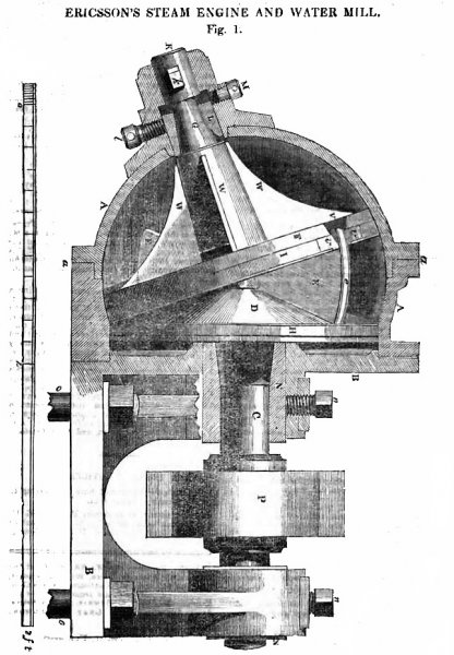
Fig. 1 represents a longitudinal section of the engine, the circular chamber being supposed to he cut through the centre-line.
A A is a circular chamber made in two parts, joined at a a, and fixed to a frame B B; this frame also supports the axis or main shaft C, to which is fixed the cone D.
EE are two wings or leaves fixed to the cone; and e is a metallic segment, fitted into a groove made in the curved edge of the leaf, and pressed towards the chamber by springs in order ta prevent the escape of steam.
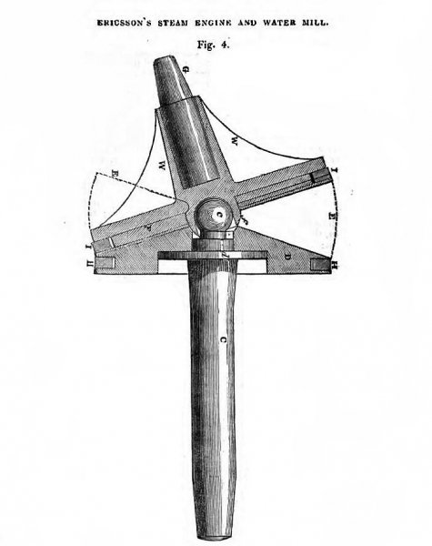
F is a circular plane, revolving on a shaft or pivot G, and supported by the main-shaft (as shown in fig. 4).
The oblique position of this circular plane, it will he seen, is so adjusted that its surface shall be parallel to, and in contact with, the side of the cone.
H is a metallic ring fitted into a groove round the cone, and divided into segments, which are pressed towards the chamber by springs, to answer the purpose of packing.
I is a metallic ring for the same purpose, fitted round the circular plane K is a cylindrical brass for the pivot G to work against e, regulated by key k.
L is a conical brass guide, kept in its place by a set-screw l.
M is a screw-pin for giving oil to the pivot.
N N are conica1 brasses for the main-shaft to work in, and kept in their places by setscrews n n.
o o are screw-bolts for securing the engine frame.
P is a pinion or small wheel, for the purpose of communicating the: power or the engine to machinery which may require a different speed.
V is one of the slits or openings, in the obliquely revolving circular plane, through which the leaves work; this slit is of equal 1egth with the leaf, and widening outwards from the surface of the plane, to accommodate the change of the angular position of the leaf, which takes place during each revolution.
v v are metallic rods, kept right against the leaf by springs, to prevent the escape of steam.
WWW are thin flat arms for supporting the circular plane.
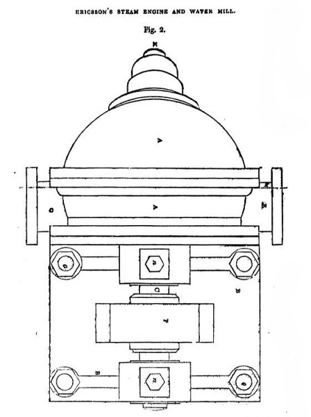
Fig. 2 represents the plan or top-view of the engine, showing the exterior of the circular chamber, the frame-work, main-shaft, pinion, &c. (it may be as well here to state, that similar letters are used to denote similar parts in all the figures.)
Q is the pipe through which the steam enters the engine, and R the pipe through which it escapes.
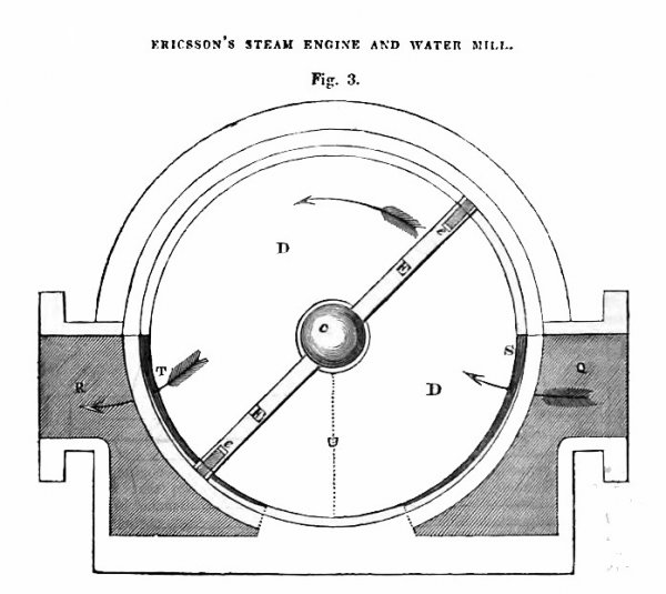
Fig. 3 is an end-view or cress section of the engine, taken through the dotted line marked in fig. 2.
The steam passes from the pipe Q into the circular chamber through an opening S cut through its side; this opening is of a triangular shape, and made as wide at the top as the circular plane is there distant from the base of the cone, and gradually tapering off downwards. T is the opening through which the steam escapes, and in every respect similar in construction.
The dotted line U shows where the cone and the circular plane come in contact. ee are the metallic segments, already described.
Fig. 4 is a detached view of the cone in the circular plane, representing a section through their centres. It will only be necessary to observe, that d is a collar on the main-shaft, by which the cone is fixed thereto; that c is a socket-ball, working in the socket f of the circular plane; and that the dotted lines EE show the precise shape of the leaves or wings fixed to the cone.
Having thus described the nature and construction of Mr. Ericsson’s engine, we shall now proceed to explain the manner in which it is set to work. Steam being admitted into the pipe Q (see fig. 3) it passes through the opening S into the circular chamber, anti being there prevented from passing the line U, where the cone and plane come in contact, it presses against the upper leaf, which, together with the cone, then revolves in the direction of the dotted arrow.
Now, as soon as the said leaf gets below the top of the opening T, the steam that has been acting escapes through that opening into the pipe R, and thence into the atmosphere or into a condenser. The opposite leaf then operates in a similar manner, and so on as long as steam is admitted.
Many as have been the engines contrived for the production of rotary motion, we recollect none in which that result has been obtained by such a perfect harmony of operation among the different parts. Not only the general action of this engine, but the action of every part of it is rotary.
The consequence is, that it is wholly free from those serious draw-backs which make the attainment of a very quick motion, by means of a reciprocating-engine, a matter of so much practical difficulty. A vast increase of power is obtained, while the bulk and weight of the material employed for the purpose are reduced beyond all former example. We shall endeavour to make this clearer by a few calculations.
The engine represented by the drawings (made to 2½ inch scale) presents to the action of the steam 12 square inches within the leaf, and is in a vertical position; but that being the maximum of surface exposed, a mean must be taken, which, by the assistance of fluxions, will be found to be ten square inches within a fraction.
By referring to the scale it will be seen, that the globular chamber of this engine is 13 inches in diameter. An engine of three times the size, that is, with a chamber of 39 inches in diameter, would, therefore, expose 90 square inches to the action of the steam; and the average distance performed by the leaf would be 7.35 feet for each resolution, and if the engine made 180 revolutions in the minute, 1,323 feet would be the distance passed in that time.
If, now, steam of 45 lbs. pressure to the square inch were used, 4,050 lbs would be the constant force in operation, which, multiplied by 1,323, shows that 5,358,150 lbs. would be raised I foot high per minute; and this sum divided by the established number, 33,000, gives for the general result, 162 horses’ power. Now, if we deduct one quarter for friction, &c., which, considering the harmonious action of the engine, is amply sufficient, the available power will be 120 horses!
That so great a power should be produced by a globular vessel of only 3 feet 3 inches diameter, is a result so extraordinary, that the attention is naturally and anxious drawn towards any probabilities by which it may be defeated. The probability of the action becoming affected by leakages first presses itself on our consideration.
On this head it may suffice to observe, that as none of the packings require any other play than to be moved gradually against their respective surfaces as they wear away, all that is required to ensure tightness will be good workmanship. The next contingency which suggests itself is the ordinary one, of liability to derangement.
On this score, however, there is but little to be feared, for the engine is of so few parts, and the mutual action and reaction of these parts is so simple and natural, that unless wantonly injured or obstructed, it can scarcely go wrong. We apprehend that the only real danger to be guarded against is the heat, which may be generated by the rubbing parts when the engine is put to its speed; between the bearings and gudgeons, in particular, as they will have to withstand a great force.
Experience can on this point be the only guide to a correct conclusion; but we incline to think, that as no inconvenience is found in cotton-mills by giving shafts of a large size, and communicating great power, a velocity of 180 revolutions per minute, any deduction to be made on this account from the utility of the engine will be but trifling. As to the packing-rings, the pressure on them will be but slight; indeed, their centrifugal force will be nearly sufficient to give them always an outward bias; the danger of their heating must therefore be extremely small.
It may not be amiss to observe, that the principle of the engine is such, that the steam may be admitted from either side with equal effect. The motion can therefore be reversed, by merely reversing the inlets and outlets of the steam by means of a common slide-valve or four way cock- a feature of this engine, which, to say nothing of its speed, must render it particularly applicable to all locomotive purposes.
The branch of steam service, however, in which this engine is likely to be adopted with greatest benefit is the marine. In steam-vessels, lightness, compactness, simplicity, are all properties of the utmost importance; and doubly so, when they can be obtained, as in this instance, without any sacrifice whatever of power.
When water is employed to work this engine, the operation will be precisely the same as in the case of steam; with this exception, that the packing rings may be dispensed with. The exception, however, is of a nature which shows that as a hydraulic engine it will work even better than as a steam-engine; of this, however, more hereafter. At present, we trust we have said enough to satisfy our readers that the great space which we have devoted to this latest wonder of the mechanical world has been not unworthily occupied.


