Stirling's 1827 patent Air Engine
Source: History and Progress of the Steam Engine
Date: 1832
Title: Patent Air Engine, by R. and J. Stirling, of Glasgow - 1827.
Author: Elijah Galloway
It has been already explained that air expands, or has its elastic pressure increased by the application of heat, and that its volume contracts, and its pressure becomes less, by a decrease of temperature; and several attempts have been made by taking advantage of this property of air, to substitute it for steam, as a prime mover of machinery.
Could this be effected, it would be a great advantage in many situations ; as, for instance, where water is scarce, or in steam vessels or locomotive engines, where (the machinery forming a part of the load,) it is desirab'e to reduce the weight as much as possible. Having said thus much of the principle of these macliines, we shall proceed to describe one or two of the latest arrangements for the purpose.
The first we shall notice is Messrs. R. & J. Stirling's air-engine, for which those gentlemen obtained a patent in 1827.
This machine resembles the steam engine in the construction and application of many of its parts, such as the piston and cylinder, reciprocating beam and parallel motion, crank, and flywheel, as shown in Fig. 1.

Motion is communicated to the piston in the cylinder, o, by alternately heating a portion of air connected with one side of the piston, and at the same time cooling that in connexion with the other. And this is effected by means of the air vessels a a, one of which communicates with the upper part, and the other with the lower part of the cylinder, through curved nozzles, m m, the pipe n forming the communication between one of the nozles m, and the top of the cylinder.
Fig. 2, represents a section of one of the air vessels, whose sides are cylindrical, and top and bottom spherical.
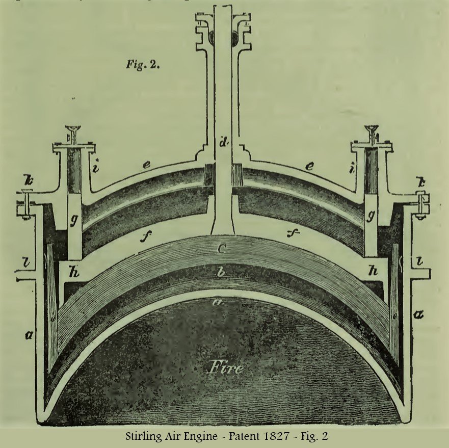
This air vessel, which is made of cast-iron, and supported in the brick-work by the projecting ledge l l, is furnished with a plunger c C c. The top and bottom of the plunger is made of strong sheet-iron, perforated with very numerous small holes to admit the air.
The interior of the plunger is filled with very thin plates of sheet-iron, so bent as to prevent their flat surfaces from coming in contact, that the air may have a free passage between them. These are also perforated with small holes, which holes are not placed opposite to each other, but so arranged as to cause the air to pass through the plunger in a zig-zag direction.
The plunger is formed circular, to fit the top and bottom of the air vessel when drawn up and down.
The patentees state, that the interior of the plunger may be filled up with pieces of brick, gravel, or other granulated substance, instead of the thin sheet-iron.
The plunger is formed circular, to fit the top and bottom of the air vessel, when drawn up and down. The rim c c of the plunger, which moves in a cylindrical receptacle at the circumference of the air vessel, as represented, is not perforated as the other part.
It is kept steady by the spring u u, consisting of a belt of thin sheet-iron, attached at its upper edge to the rim c c; a number of slits are made from the lower-edge of the belt, to admit of its being bent outwards, to rest against the air vessel, and act as a spring.
The plunger is also kept already in its ascent and descent, by the plunger-rod d, passing through the stuffing-box at the top of its case, and the guide rods g g, which work in the guide cases i i figs. 1, and 2.
The guides are fixed to a ring h h, which is attached to the plunger and the plunger-rod, by the arms f f, four in number. They are supplied with oil, by an oil cup and stop-cock at the top of their cases. The top e e of the air vessel is flanged down in the manner represented at k, with a thin ring of sheet lead between the flanges, to keep the joining air-tight.
The lower part of the air vessels is heated by a fire place under it, and its upper part kept cool by a current of cold air, by water, or by other means.
The plunger-rods of the air vessels a a, fig. 1 are attached by slings to the ends of the beam v so that the motion which elevates one plunger in one of the vessels depress that in the other.
When the plunger is raised, the cold air in the upper part of the air vessel will be heated in passing through the interstices of the plunger in its ascent, which has itself been heated on reaching the lower or hot part of the vessel, and during this time the air in the other vessel will be cooled, by passing through the interstices of the plunger in its descent, which has itself been cooled by reaching the upper or cold part of the vessel.
These changes of temperature are further augmented, by portions of the air being alternately changed from the hot to the cold, and from the cold to the hot parts of the vessels, by alternate occupation of the hot and cold parts by the plunger.
Now, as one of the air vessels is connected with the top, and the other with the bottom of the working cylinders a, there will he a motion produced on the piston, by the alternate application of the expansive force of heated air, and this motion is communicated to the beam v, through the piston rod and parallel motion q, and to the connecting rod at the other end of the beam, and the crank r, to the fly-wheel s s.
On the axis of the fly-wheel is fixed as eccentric l, which communicates motion to the plungers in the air-vessels, through the system of levers 1, 2, 3 ,4, and the beam v; and this motion is adjusted so that the change of the plungers shall he effected, whenever the piston reaches the top or bottom of the cylinder; thus applying to that end of the cylinder where the piston is, the hot air, which, by its increased elasticity, will drive the piston to the other end.
The diameter of the nosles, m, is one-fifth the diameter of the cylinder o, and one-fifteenth of the diameter of the air vessel a.
This engine is also furnished with an air-pump, the piston rod of which is shown at x, for condensing air into the air reservoir w, w. The air is permitted to pass through self-acting valves into the nosles m m, and thence into the cylinder o, or the air vessels a a, but not permitted to return from these vessels or the cylinder into the reservoir, which is also provided with a safety-valve for the escape of superfluous air, when more is pumped in than is necessary to supply the air vessels.
The air-pump is only occasionally required to be set to work.
The diameter and length of the stroke of the air-pump are half those of the cylinder, but this appendage is not required to be kept constantly at work.
The patentees state, in their specification, that any of the permanent gases may be employed, instead of atmospheric air. They do not claim, as their invention, the application of these bodies to produce motion; but merely the foregoing arrangement of machinery, for applying the elastic force of gaseous bodies to the production of motion.