Lehmann's air expansion engine
The Lehmann hot air engine is a technological marvel born in Germany.
 |
|
| Inventor | Wilhelm Lehmann, of Nuremberg, Bavaria, Germany. |
| Country | Germany |
| Year | 1867 |
| Patent | Yes |
| Operation | Closed cycle |
| Combustion | External |
| Engine type | One cylinder |
| Working piston | Single acting |
| Output | 0.5 HP to 4 hp |
| Fuel consumption | Coal |
History
By 1850, England, America and France had delivered to the World several remarkable hot air engines. Surprinsingly Germany had not yet brought any notable innovation in this field and it was only in 1867 that this country came up with a major innovation in hot air machine. A late innovation, but a stunning one: the Lehmann air expansion engine !
This hot air machine or, as its inventor more aptly names it, the "Luftexpansionsmaschine" has been brought to fruition by the German engineer Wilhelm Lehmann of Nuremberg (Germany) in 1867 and was exhibited at the Universal Exhibition of Vienna in 1873.
This engine has quickly become a great success throughout whole Europe, especially in German speaking countries. As Alfred Musil wrote in 1875 : "Lehmann’s hot air machine is the oldest and also the most widespread of the currently renowned constructions."
Wilhelm Lehmann, inventor of one of the most popular and best-reputed hot air engine of the 1860s, has been completely forgotten. His name has been lost, hidden in the ditches of History. Fortunately, some excellent archives provide a profound insight on one of the best hot air engine ever made.
Engine Arrangement
The engine description that follows has been done on the basis of the drawings which the inventor himself has given to The Polytechnische Journal (link at the end of the page).
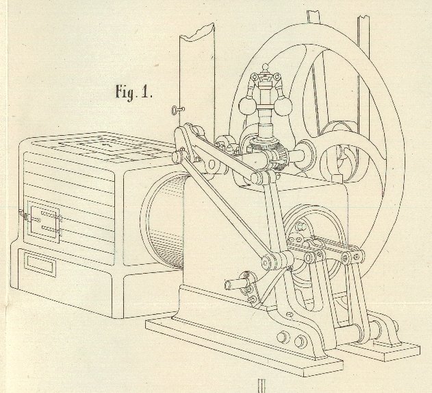
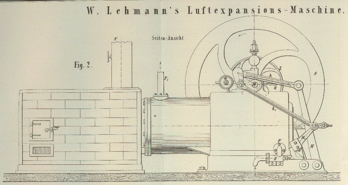
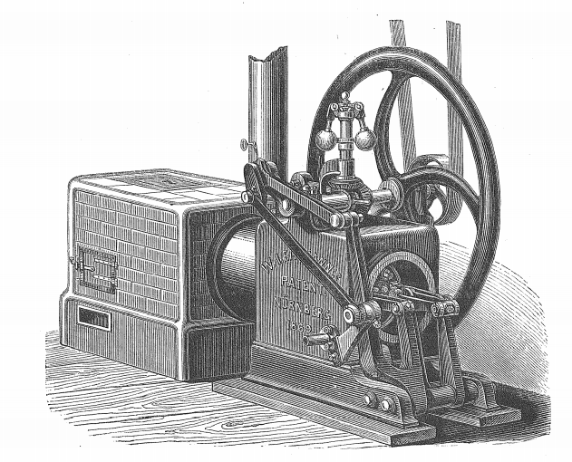
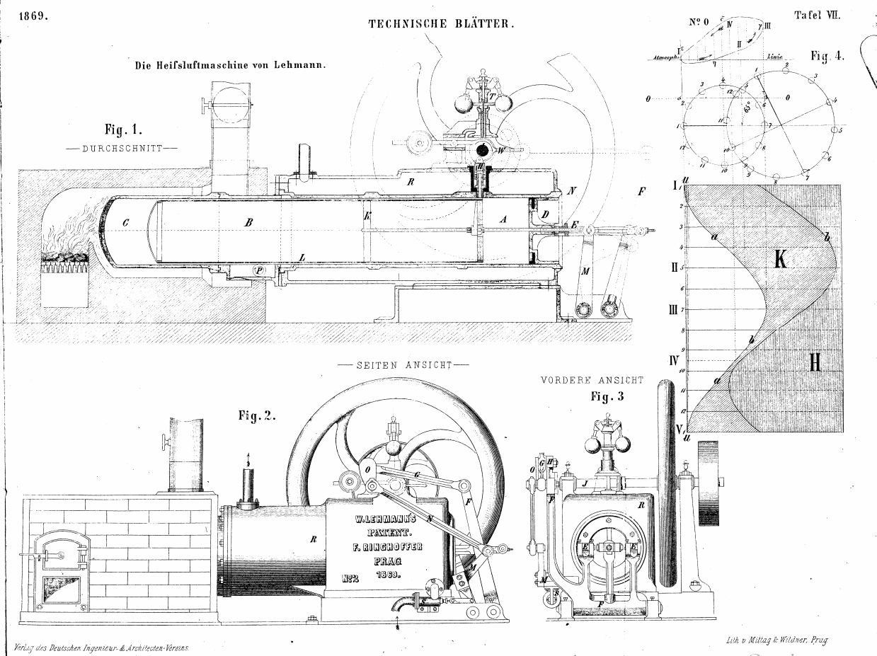
Fig 1 and 2 give a general view of the engine.
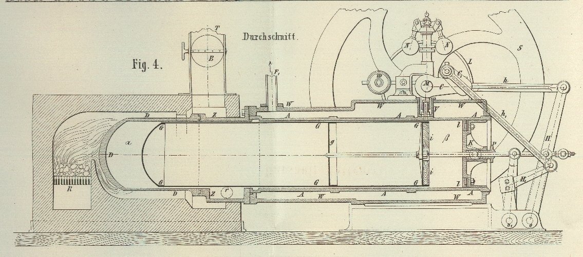
Fig 4 is an elevation that gives an easy understanding of the machine construction, and its operation.
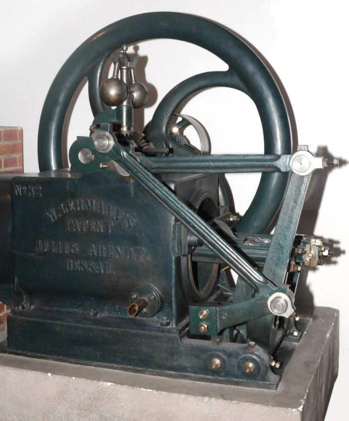
The Lehmann's air expansion machine consists essentially in a long cast-iron cylinder A, A, which is fitted in a cast-iron jacket W, W. The cylinder A, A has a continuation through a cast-iron cylindrical piece Z, Z and a ending consisting in a cast-iron fire pot D, D
The cylinder A, A and its jacket are positioned outside the furnace where is located the grate R. The other components are inside the furnace, with the fire-pot D, D touching the flames coming from the grate R.
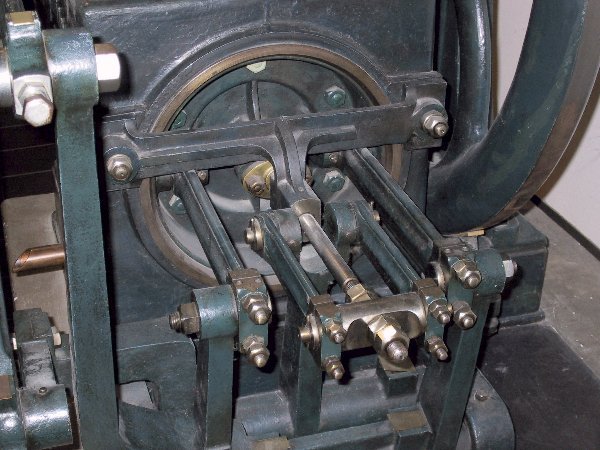
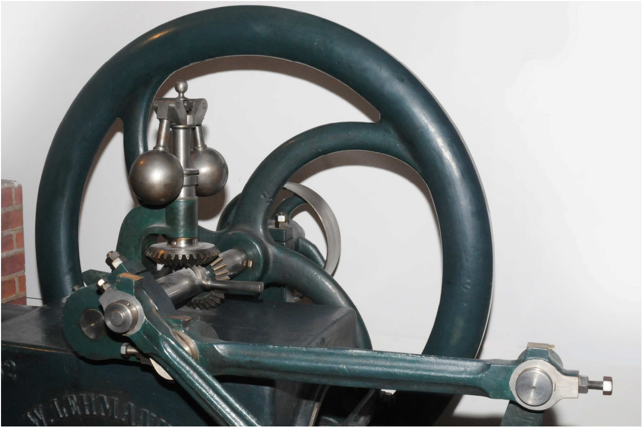
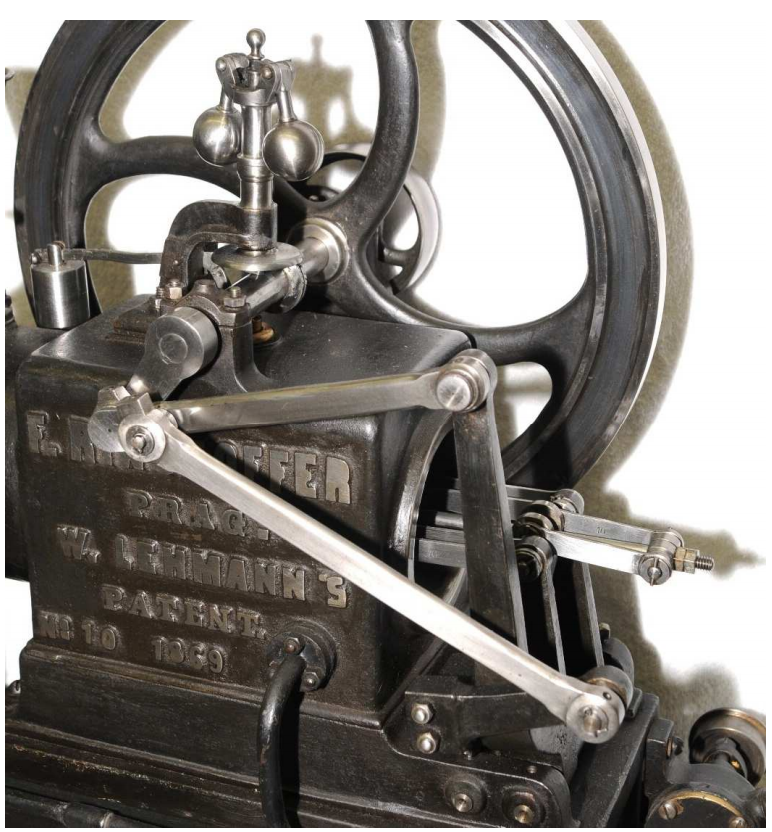
The whole cylinder AA, ZZ, DD is closed by the fire-pot D, D that is the heater and is located within the furnace. On the other end the cylinder is closed by the piston K. This piston is connected by rods with the fork-shaped lever H and the rod h to the crank C of the flywheel shaft M in such a way that a reciprocation of this piston K causes a rotating movement of the flywheel shaft M.
In this cylinder AA, ZZ, DD there is a displacer or a distribution piston made of an airtight riveted metal sheet cylinder G, G, which is stiffened in the middle by the disc g and provided in front with a rod which penetrates airtightly through the stuffing box P of the piston K and is connected to the flywheel axis M of the engine by the lever H' the pull rod h' and the counter crank C’.
This metal sheet cylinder is moved by the machine and is thus considered to be passive in the movement of the same.
The fire pot D, D, as well as the intermediate piece Z, Z are walled in a small furnace and are heated by the fuel burning on the grate R. The front part of the cylinder A, A is inserted, as already mentioned, into the jacket W, W and is constantly cooled by cold water, which runs from a special reservoir into the cavity between the cylinder A, A and the jacket W, W.
S is the flywheel, which has its center of gravity in the middle without being overweight. The force is transmitted by the belt shaft L. N is a regulator of the simplest form, which, if the movement is too rapid, opens the bell valve V outwards, so that a part of the enclosed working air escapes and the machine can resume the pressure corresponding to the normal number of revolutions. The same valve also serves as a shutdown device and is opened by the handle Q, but otherwise maintained closed by a counterweight w, as can be seen from this figure..

The the small pump E can be seen if fig. 2 and also fig. 3. It supplies the machine with fresh water. At F, the cold water penetrates into the cylinder envelope and after warming up flows back into the reservoir. Where a water pipe is available, the pump is eliminated. Its sole purpose is to maintain the water in constant, lively circulation when a reservoir is used.

The metal sheet cylinder G, G, which forms the distribution piston (also called the displacer), deserves a more detailed discussion. This cylinder is made of a riveted 1 1/2 millimeter thick iron sheet. It has to be airtight in all parts as it were to form a cylinder made of a material which conducts heat poorly (air is a poor heat conductor). The air that is trapped within it, in conjunction with the cylinder thin sheet metal wall meets this requirement.
Its guidance in the main cylinder is obtained partly by soldered strips, partly in the stuffing-box of the piston K. Moreover, in order to reduce the friction in its course, as far as possible, it rests on a loose roller r (Fig. 4). This roller does not have a tenon, but rolls back and forth only in the roll-keys of the part Z, Z, and thus makes only half of the way which made by said metal sheet cylinder G, G. This metal sheet cylinder is first moved by the machine all the way to the rear bottom of the fire pot D, D, and then all the way back to the piston K. In order to fill the harmful space of its front side, it has a wooden disc i, i (see Fig. 4).
The working piston K is sealed with a leather cuff l, which is mounted from the inside. It tightly seals the cylinder from the outside air as soon as there is tension (or pressure) in the machine. On the other hand, in case the air pressure within the cylinder lowers below the external pressure, it allows the outer air to penetrate the cylinder.
Its effect is therefore similar to that of a one way valve (or non-return valve), which opens towards the interior of the cylinder.
The counter-crank C' which moves the distributing piston or displacer, is set in such a way that it advances the engine crank C by an angle of 32 1/2 °. Moreover, since the axes of the two crank mechanisms are also inclined at an angle of 32 1/2 ° to each other, the movement of the displacer is as if the counter crank of the power crank would lead by 65 °, with the axes of the two crank mechanisms falling on each other.
Operation
Let's imagine the machine in the heated state, supplied with the necessary amount of cooling water, and the crank in the position as in Fig. 4. The working piston encloses an air volume which is the difference between the volume of the cylinder AZD, AZD and the volume of metal sheet cylinder G, G; this is the working air volume.
A single-horse (1 HP) machine has the following dimensions:
- Working piston diameter : 13 1/4 inches (34.9 cm)
- Stroke of working piston : 6 5/8 inches (17.45 cm)
- Displacer diameter : 13 inches (34.23cm)
- Length of the displacer : 58 inches (152,73 cm)
- Stroke of the displacer : 9 1/4 inches (24.36 cm)
After the displacer is up to 1/8 inch (3.29 mm) into the heating pot and the working piston is in its outermost position at the open end of the main cylinder, the distance between the two pistons is 12 7/8 inches (33.9 cm). This represents an air volume of 1775 cubic inches (0.0324532 m3). The total volume of the air enclosed, with the addition of 300 cubic inches (0.0054858 m3) is 2075 cubic inches or 0.037945 m3.
This volume of air is compressed by the motion to the inward of the working piston, and at the time the piston is at the end of his stroke, this compressed volume is of (12 7/8 – 6 5/8) × (13 1/4)² . π/4 = 1162 cubic inches or 0,021251 m3.
Since the heat generated by the compression enters in any case the cooling water, the temperature of the air thus remains unchanged. According to Mariotte's law, the tension of the air at the end of the compression strike should be 2075/1162 = 1.79 of the initial tension (or pressure), provided that no air losses take place. In the actual experiment, this compression ratio has turned out to be 1.74.
The move of metal sheet displacer G, G towards the end of the pot D, D displaces the hot air found at α that will have to find its way back to β, passing along the walls of the displacer G, G. In doing so the air is divided into a very thin layer, and by giving off during its journey its heat to the cold working cylinder A, A, it reaches β as cold air.
The hot air can never act as such on the working piston, since, as often as it reciprocates from α to β, it loses its heat up to the temperature of the cooling water.
The engine power generation
The cooling is all the more perfect as the cooling surface is comparatively very large. Since the metal displacer G, G extends to the bottom of the fire pot D, D, the entire volume of air is forced to cool.
Conversely, if we consider the plunger G, G moving toward the piston K, and at the same time this very piston moving to the inside of the cylinder, then the cold air volume at β will be displaced to α while undergoing compression.
When reaching the hot rear part of the metal plunger G, G where are located the hot intermediate piece Z, Z and the red-hot pot D, D, it will take up heat again very quicly.
When the displacer G, G approaches the piston K so that the volume β = 0, then the entire enclosed volume of air is at α.
Whatever the position of the displacer and the piston K, the air volumes enclosed in β and α are always in communication thanks to the gap between the displacer and the main cylinder. As a result, during the operation, the pressure in the hot room α will be almost equal to the one in the cold room β.
On the other hand, the air temperature in both rooms will be very different and indeed will depend on the temperature difference between the cylinder walls submitted to the impact of the fire, and the cylinder wall undergoing the impact of the cold water.
This is where the intermediate piece Z, Z plays a crucial role in partly stopping the heat propagation between the fire-pot D, D and the cylinder part A, A; a secondary reason being the ease of maintenance of the air engine.
For each position of the crank and the piston the density of the air in the hot room α will necessarily lower as the higher the temperature there will cause a higher the pressure in the whole machine, while in the cold room β this higher tension will increase the air density.
Therefore the air in both rooms has almost the same pressure, but in one room this tension is due to the high temperature, in the other to the high density; thus there is expanded heated air in one room and compressed cold air in the other.
Nonetheless the pressure of the enclosed air will vary significantly during a crank turn and at each instant depending on the position taken by the piston and the displacer, so that any inward movement of the piston generates air compression and any outward movement air expansion.
The power of the machine results from the increase in pressure of the air in room α due to the heat. This pressure is communicated to the cold air present in the dead volumes which in turn does work on the piston K. The move back and forth in the right proportion of the displacer and the piston alternatively move the hot air to the cold side and the cold air to the hot side. In doing so it increases and decreases the pressure in the machine and, consequently generates its motion.
Each loss of air replaces itself in one revolution through the leather cuffs l, so that a reduction of the working air volume can never occur.
The above description makes clear the working and the mode of operation so that in this respect, hardly any further, explanation is necessary.
Comparison with existing hot air engines
A certain volume of atmospheric air is compressed by the cold temperature of the cooling water present in the machine to about one-half to three-quarters of an atmosphere. The increase in temperature due to the air compression, albeit certainly very low, is immediately transferred to the cooling water. The compressed air is then led in form of a very thin layer over hot surfaces, whereby it absorbs heat and thereby increases in temperature and tension.
The work resulting from the alternating heating and cooling of the volume of air, is transferred to the machine in an indirect way as the hot air does work on the piston K not directly, but, as already indicated, only indirectly by mean of the cold air.
In this respect the Lehmann machine differs essentially and advantageously from the Laubereau hot air machines, with which it otherwise agrees most in principle and arrangement.
The movement of the working piston and distribution piston is almost identical in both machines. But while in Laubereau's machine the heated expanded air acts directly on the working piston, in Lehmann's machine the heated expanded air, as we have seen, serves only to compress the cooled air. This is achieved by means of the thin layer surrounding the distribution piston (displacer), which is a poor heat conductor, and being exposed to constant cooling, is able to transfer pressure but no heat.
The working-piston in Lehmann's machine, therefore, is subject only to the action of cooled compressed air, while in Laubereau's machine it is exposed to the direct action of the heated air.
This is where lies the main evil that sticks to the well-known Laubereau machine, and which Lehmann happily avoided in his machine. It is worthy of note, that Ericsson already solved this issue when building his new caloric engine (of 1863), in avoiding the direct action of the heated air onto the working piston. Albeit he did it in a much less elegant manner than Lehmann.
Moreover, the Lehmann machine, like the Laubereau and Ericsson machines, is single-acting and requires a correspondingly heavy flywheel to obtain a smooth gear, but, as has already mentionned, the attachment of a counterweight can be omitted.
Running the machine
As far as the operation and heating of the Lehmann machine is concerned, it is very simple and does not require a special machinekeeper, but rather can be taken care of by every worker. To start up, all you have to do is heat the stove for 15-20 minutes, starting the fire first with wood and then maintain it with charcoal. To start the crank of the machine must always stand on the front dead point, i. This means the working piston must be at its outermost position. The crank being in this position the displacer is not exposed at its rear end to the high temperature of the fire pot.
By the time the machine is heated, a small impulse given to the flywheel in the direction indicated by the arrow is sufficient to start the machine.
The stopping of the machine is done by opening the valve (Fig. 5) with the handle, and the crank will need to come back to the same position as for starting.
The power of the machine depends directly on the temperature of the fire-pot, and care must be given to preserve it in regular heat by timely re-firing.
The head of the fire pot should never turn bright red; a dark vermilion coloring is sufficient. All rubbing parts are to lubricated in a good manner; likewise the inner part of the working cylinder, as far as the rearmost position of the piston permits, is to be coated with good oil.
The number of revolutions of the flywheel should not exceed 100 rpm during work. Therefore at 120 revolutions per minute, the valve will be opened by the regulator and will blow off. As already seen, the air lost during the course due to the the piston and valve leakage is replaced during work, since so much air always penetrates inwardly through the working piston than the machine requires.
Reservoir and cooling water consumption
The cooling water temperature in the machine should usually not be over 44-50 ° C. This should not happen with a good circulation and a sufficient water reservoir. Where local conditions permit, a water pipe is used for this purpose and then the inflow can be easily regulated so that the effluent water reaches said temperature.
However, if the reservoir is not installed near the machine because of local conditions, but is placed lower, then, as indicated in our drawings, a small auxiliary pump is to be used, which is moved by the machine itself. It requires little force, provided that the water flows back into the reservoir. No other mechanical work is necessary, than to maintain the cooling water in a gentle motion.
Of course, the drainpipe must open slightly below the water level of the reservoir. If, however, the fact that the new machine requires the cooling of the trapped hot air of the cold water is one of the weak points of this machine system, the consumption of water, which its operation requires, is not so great as to be an obstacle to it Presentation of the machine.
The cooling of the enclosed hot air by cold water is one of the weak point of this machine. However the water consumption necessary to operate the machine is low and shall not be an obstacle to its erection. The water can be heated up to 50 ° C. and even more, without being a hindrance to the machine operation. Therefore a water consumption of 5-10 cubic feet to the horsepower (140 - 280 liters) should be sufficient for running it.
Fire
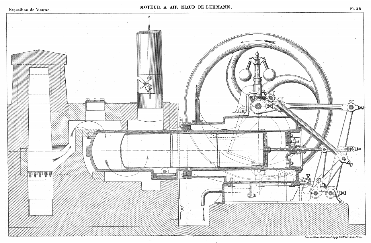
The furnace is a completely conventional grate furnace, which is located somewhat behind the fire pot and, as can be seen from FIG. 2, is heated from the side. The combustion gases surround the fire pot D, D and the cylindrical extension Z, Z as far as possible from all sides before they move into the chimney T, in which an ordinary furnace flap B is attached for regulation.
Coal consumption
Considering a working day of 10 hours, the coal consumption for a 1 HP machine is around 80-100 lbs (36 - 45 kg), that is an average of 3.6 - 4,5 kg per HP per hour. This is indeed a high combustible consumption and shows that the furnace should be set up more appropriately.
As a comparison, the combustible consumption of the Woodbury hot air engine was around 1,5 Kg per HP per hour.
Distinctive features
The most remarkable advantages of the new air expansion machine, according to what has been said so far, are as follows:
1) The machine runs completey silently;
2) All rubbing parts work in cold condition and can therefore be lubricated with ordinary oil and consequently suffer little wear;
3) since the air working in the machine always remains the same, the operation of the same does not degrade the ambient air, and since that air works constantly in a cold state, the otherwise unpleasant smell of oil does not occur ;
4) it can be set up anywhere without any substructure on higher floors and a simple indoor fireplace is sufficient for its operation;
5) as with any hot-air machine there is no danger of explosion and therefore no official authorization is required for its installation and therefore it does not cause a higher insurance premium for any fire insurance;
6) no skilled attendant is required as the machine operation and heating is simple and can be conducted by any boy or worker;
7) the heating of the machine can also be used with advantage for cooking, as well as for heating the work place;
8) that any fuel other than coal is to be used for their heating (except Kohks);
9) that it does not require long pre-firing, but can be started after 15-20 minutes of heating, as well as that because it is not possible to overheat it can be switched off in the heated state for any length of time without this to suffer in the least;
10) the water necessary for cooling the air, at least with a sufficiently large reservoir, can always remain the same, because it cools itself down in the air, and that this cooling water, because it remains clean from all earthy and contaminating parts, can also be used with advantage for various purposes as warm water;
11) the machine is an extremely simple and easy-to-understand construction, should anything be missing inside it, it can be put apart and reassembled in a few minutes;
12) Finally the purchase price is very moderate compared to other similar machines.
Limitations
In addition to the heating and water pipes, we also have a few other points here that could affect the performance of the machine. This includes any leaks in the connections of the piston, the valve and the stuffing box. Any leakage of these parts can be noticed immediately by compressing the air, when the flywheel is forcibly turned from the foremost piston position when the machine is cold. The compressed air will then, if there is no leak, drive the piston back almost to its original foremost position. If this is not the case, it is because of leakage.
If the air is compressed in this way when it is cold, it reaches a tension of 8-12 PSI (0.5 to 0.8 bar) above the normal atmospheric pressure when the working piston is in the end position.
The leakage of the inner sheet metal cylinder is also detrimental to the performance of the machine, because the tension in the working air, as it penetrates into the inside of the sheet metal cylinder, is of course much lower than if the sheet metal cylinder G, G were to close tightly. This leak is all the more worrying because it cannot be perceived directly. But the manometer gives indirect information about the low level of air pressure and if this sign really occurs, the matter must be examined immediately and the leaks in the sheet metal cylinder must be improved.
Finally, there can also be frictional resistances on the inner sheet metal cylinder, which have an adverse effect on the machine's efficiency. If this cylinder is otherwise in order, it does not require any special lubrication, since some oil is always sucked in through the working piston with the air. On the contrary, bad and thickened oil are often the cause of the strong friction. In this case, the working and sheet metal cylinders must be cleaned. If, on the other hand, the sheet metal cylinder grazes in the fire pot, which, incidentally, is immediately audible, in most cases this problem can be remedied by turning the cylinder into another correct position.
All of these defects and shortcomings, which could possibly arise with the new machine, are such that they can be easily lifted and removed in each individual case. Since it now has several very significant advantages against most of the other hot-air machines known to date, there is no doubt that it will find a good reception everywhere, especially in small businesses and especially for small operators up to 2 horsepower.
Manufacturers of the Lehmann air expansion machine
Within a few years «Lehmann» engines of horizontal design were widely used. Between 1871 and 1873 about 130 were made in Germany. It is reported that more than 1,300 Lehmann air engines were built till 1878. From there on, because of a small but decisive change - cast steel was used for the fire pot instead of iron steel - sales just boomed.
Wilhelm Lehmann did not manufacture his air engine by himself. The patent rights for the German states and foreign countries were acquired by several manufacturers:
- C. Völckner and H. Nehrlich in Aschaffenburg, Bavaria - Germany
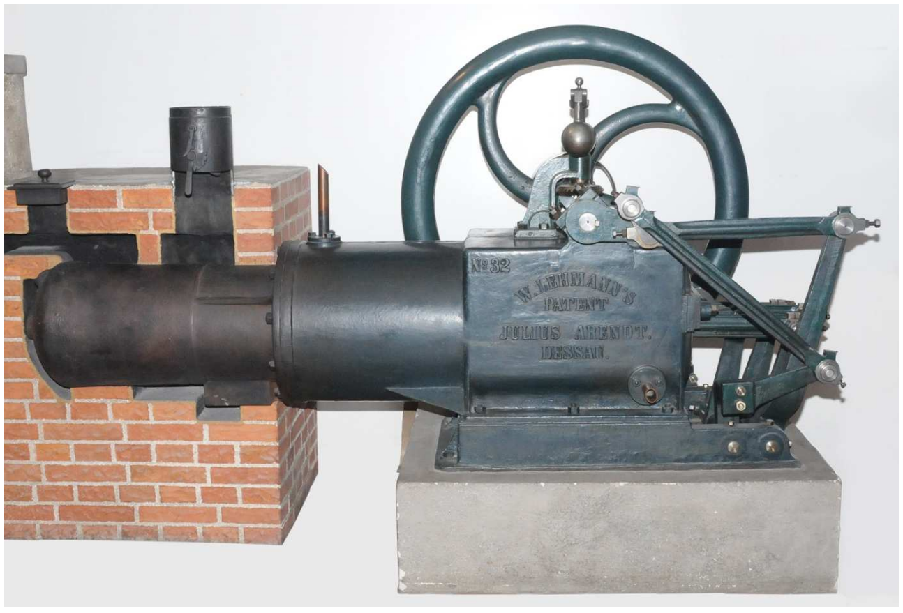
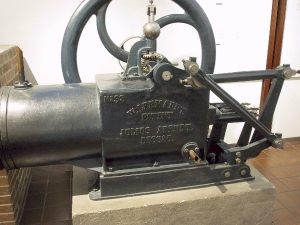
- Julius Arendt, Dessau - Germany. The company was merged with Öchelhäuser & Blum, Berlin, to form the BAMAG (Berlin-Anhaltische Maschinenbau-Actiengesellschaft) which had its headquarter in Berlin and Dessau and which kept on building the Lehmann engine
- Webstuhl- und. Maschinenfabrik formerly May & Kühling, Chemnitz, Saxony - Germany
- Franz Ringhoffer in Smichow near Prague - Austrian Empire
- W.H.Bailey Albion Works, Manchester - England
- W.H.Bailey Albion Works with agent J.C.Mackinnon, Sydney - Australia
- Stehn & Wulfing, New York City - America
Several licensed manufacturers did improvements on the original Lehmann engine, and some of them patented their imrovements: BAMAG, BAILEY. They used them to manufacture the engine under their own name.
Soon after acquiring the patents rights, Ringhoffer's machine factory and iron foundry in Smichow, Prague carried out 6 Lehmann machines, and C. Völckner and H. Nehrlich announced their taking of orders for the construction of this machine, from which following figures regarding the its dimensions and prices are taken:
| Power of the machine in horse power | 1/2 | 1 | 2 |
| Number of working cylinders on a machine | 1 | 1 | 2 |
| Cylinder diameter in millimeters | 263 | 378 | 378 |
| Entire length of the machine in millimeters | 2400 | 2800 | 2900 |
| Entire width of the machine in millimeters | 800 | 1000 | 1000 |
| Entire height of the machine in millimeters | 1150 | 1500 | 1100 |
| Number of revolutions per minute | 100 | 100 | 100 |
| Price in Thalern (Reichsthalern) | 400 | 500 | 600 |
The prices are quoted loco Aschaffenburg netto comptant.
| Gallery | ||
|---|---|---|
|
|
 |
 |
 |
 |
 |
 |
 |
 |
 |
 |
 |
 |
 |
 |
 |
| Archives for download |
|---|
| August Salaba - Versuch einer Theorie der Lehmann'schen calorischen Maschine |
| Gustav Schmidt - Theorie der Lehmann'schen Calorischen Maschine |
| Interesting pages |
|---|
| Video - Model Lehmann air engine |
| Video - Model Lehmann air engine |
| Dipl.-Ing Gerd Maier's hot air engine story |
Sources of information
| Document | Author | Date | Title |
|---|---|---|---|
| Technischen Blättern | W. Eckerth | 1869 | Die Lehmann'sche Heißluftmaschine |
| Polytechnische Journal, Band 194, Nr. LVIII. (S. 257–284) | G. Delabar | 1869 | Fortschritte bezüglich der Dampf-, Gas- und Heißluftmaschinen |
| Zeitschrift des Vereines Deutscher Ingenieure | Gustav Schmidt | 1871 | Theorie der Lehmann'schen Calorischen Maschine |
| Zeitschrift des Österreichischen Ingenieur- und Architekten-Vereins | A. Salaba | 1871 | Versuch einer Theorie der Lehmann'schen calorischen Maschine |
| Exposition de Vienne - Description des machines | Hippolyte Fontaine | 1874 | Moteur Lehmann |
| Die Motoren für das kleingewerbes | Alfred Musil | 1875 | Heißluftmaschine von Lehmann |
| Annales des mines - Tome XVI | Luchard | 1878 | Machines à feu diverses - Lehmann |