Wenham's Heated Air Engine
Source: an article from the Institution of Mechanical Engineers - Proceedings
Date: 1873
Title: On Wenham's Heated-air Engine
Author: Conrad W. Cooke
The class of heated-air engines of which that forming the subject of this paper is a type consists of those in which the fire is enclosed, and fed by air pumped in beneath the grate in sufficient quantity to maintain combustion, while by far the largest portion of the air enters above the fire, to be heated and expanded; the whole, together with the products of combustion, then acts on the piston, and passes through the working cylinder; and the operation being one of simple mixture only, no heating surface of metal is required, the air to be heated being brought into immediate contact with the fire.
The first successfully working engine on this principle was Cayley's, in which much ingenuity was displayed in overcoming practical difficulties arising from the high working temperature.
The plan of enclosing the fire in the mass of air to be heated involves the utmost degree of economy, as there is nothing whatever lost in the absolute heating, and the products of combustion, varying in quantity according to the fuel employed, also add to the bulk of the mixture. These principles are embodied in the heated-air engine forming the subject of the present paper, which is the invention of Mr. Francis H. Wenham, the inventor of the binocular microscope, whose researches and inventions in many branches of science are of so much value.
In this engine, which has been very successful for small sizes, a peculiar feature is that no separate air-pump is used the top of the working cylinder itself being employed for that purpose. This is not a new idea, as Ericsson proposed utilising the top of the working cylinder in that way ; but he never carried it out practically.
The air-pump however must necessarily be of less capacity than the cylinder according to the degree of expansion required to be given by heating the smaller volume of air pumped in ; and means had consequently to be devised for diminishing the capacity of the air-pump with the same diameter of cylinder, so that one piston packing might serve for both air-pump and working cylinder.
This difficulty was overcome by the President of the Institution, Mr. C. William Siemens, who diminished the air-pump space by attaching to the piston a hollow trunk working through a stuffing-box in the cylinder-cover. Thus if the trunk were made one half the diameter of the cylinder, it would abstract one fourth from its capacity ; and such an arrangement was employed in Mr. Siemens' regenerative steam engine, which would also work as an air engine or with air and steam combined.
Wenham's engine of one horse power is shown in Figs. 4 to 10.
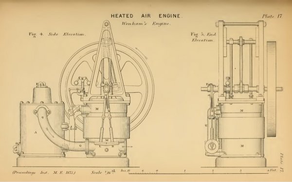
One of its special features is the furnace or air heater A, shown in section in Figs. 6 and 9, in which perfect combustion is obtained from ordinary smoking and bituminous coal; and coal of that description is preferred for this engine.
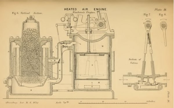
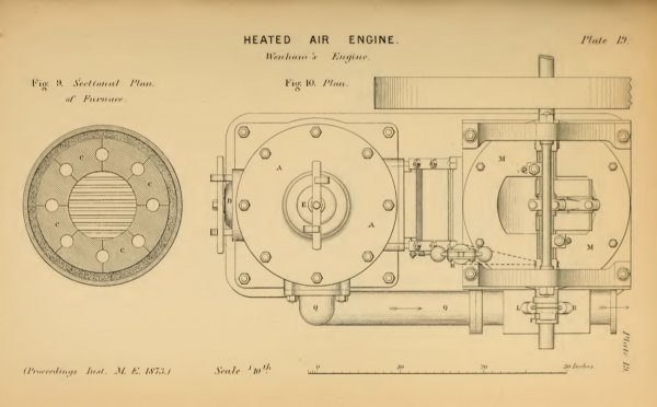
The ashpit B or compartment under the grate is separated from the upper part by a moderately air-tight diaphragm, so that the air that is allowed to enter the ashpit is compelled to pass up through the fire grate. Above the grate is an annulus of segmental firebricks C C, shown in the sectional plan, Fig. 9 ; these bricks are made with semi-cylindrical grooves at their joints, so that when placed together, the centre forms a cylindrical hopper containing a store of fuel sufficient for several hours' consumption, and the grooves at the joints form a series of vertical flues or channels through the bricks.
The column of coal descends as it is consumed on the furnace bars, and the air entering from the ashpit comes into contact with nothing but coal in a state of intense ignition ; all the products of combustion have accordingly to pass through the iognited portion, and the channels or flues in the firebricks being also white-hot, no unconsumed products or smoke can escape through them.
The furnace has a cover D in front of the ashpit, by which it can be hermetically closed ; and there is a similar cover E at the top for filling the coal hopper. The products of combustion after leaving the channels of the firebricks C are met by a baffle plate P backed with fireclay, which prevents the cover of the furnace from getting unduly hot. The space between the firebricks and the outside shell of the furnace is filled to a level a little below the air passage leading to the cylinder with a slow conductor of heat, such as powdered brick or ashes, leaving an air space above that level.
There are two inlet air passages G and H, Fig. 6, for admitting the cold air to the furnace; the passage G conducts the air into the ashpit below the fire, and the other H leads above the fire; at their junction is placed a swing valve J, by which more or less of the air is directed below or above the fire. If all the air be directed below the fire through the passage G, the combustion will become very intense; the heat and consequent expansion of the air will become correspondingly great, and the engine will gain in power and speed.
If on the other hand all the air be directed above the fire through the passage H, a very dull fire will be the result; the air will be comparatively cool, and will be less increased in volume, and there will be a diminution in the power of the engine.
This difference of power is found to take place so instantaneously that the regulation of the air distribution serves as a very effective means of regulating the speed of the engine, and the governor K is consequently attached to the lever of the swing valve J; this arrangement is found to act so perfectly that no other regulation for speed is required, and it gives the advantage that the combustion of the coal is exactly proportioned to the amount of work performed.
The engine is of the vertical form, having two piston rods with the main or crank shaft running between them, as shown in the plan, Fig. 10; and in order to save space and render the cylinder M as compact as possible, the cylinder cover is made with a segmental recess or depression in which the crank passes, as shown in Fig. 6.
The engine is single-acting, the upstroke only being made by the pressure of the heated air below the piston N, and the engine is carried through the downstroke partly by the expansion of the cold air compressed above the piston in the upstroke, and partly by the flywheel.
The heated air from the furnace passes along the curved pipe Q, and is admitted at the bottom of the cylinder by the lifting valve L, which is opened by a cam P on the main shaft, as shown in Fig. 7 ; a lifting valve is required to be used, as a slide-valve will not answer. The exhaust valve R is of similar construction, and is also opened by another cam, as shown in Fig. 8 ; and both valves are closed by the spring S.
In this engine the protecting drum under the piston N, Fig. 6, which was first brought out in America, is adopted for preserving the working surfaces of the cylinder and piston from the wearing action of the sohd products of combustion. This drum is useful only in a single-acting vertical cylinder where the working pressure acts only on the underside. It is simply a prolongation of the piston, in length exceeding by a small extent the stroke of the piston, and is a little less in diameter than the cylinder, leaving a small annular space between the two.
The packing ring of the piston being near the top, the dust cannot get to it, and the bright working part of the cylinder traversed by the packing ring is never uncovered or exposed to the direct action of the dust and heated gases. Any dust entering the cylinder from the furnace is blown out at the exhaust from the bottom.
The piston is lubricated with dry plumbago powder, and in practice the cylinders are found to maintain a good working face, and to be as durable as those of steam engines ; in fact it is found that a film of black-lead taking; a high polish is continually being deposited upon the inner surface of the cylinder, and the cylinder has as great a tendency to diminish in diameter from this cause as it has to be worn larger by friction.
The chief peculiarity in this engine is the arrangement by which the top of the working cylinder serves as the air-pump, and is made to deliver into the furnace for expansion the reduced bulk of compressed air required for performing the work.
At the top of the stroke the piston does not reach the cylinder cover, but a considerable clearance space is left between them, the capacity of which has been determined by experiment so as to give the best effect; the result arrived at is that the pressure in the furnace should never exceed 15 lbs. per square inch above the atmosphere. In the first portion of the upstroke the air contained in the air-pump is compressed to half its volume, or to a pressure of 15 lbs. per square inch, and not till then does there exist equilibrium between the air in the air-pump and that in the furnace; the delivery valve T then opens, as shown in Fig. 6, and during the remainder of the upstroke the air is pumped into the furnace.
At the end of the stroke the valve T closes, leaving still 15 lbs. pressure in the space above the piston; and as there is no further escape for this, it acts upon the piston during part of the downstroke, and equalises the action of the engine to such an extent that a small flywheel only is required.
This is not put forward as any advantage in power, because whatever force is required in order to obtain the pressure of 15 lbs. above the piston must be deducted from that of the upstroke; it is but transferred from the lower side of the piston to be utilised above it in the subsequent expansion of the compressed air.
As soon as the air above the piston has expanded down to atmospheric pressure in the downstroke, the inlet air-pump valve U opens and admits the quantity of cold air required for the next stroke of the engine. By holding open this valve by means of a small hand lever placed below it, the cold air is merely pumped through it in and out of the air-pump, none going into the furnace, and the engine is thereby stopped.
In order to start the engine, in the case of those of small size a few backward turns are given to the flywheel by hand, while the top cover is off the furnace; and from the arrangement of the valves it will be seen that when the flywheel is turned the reverse way the cylinder is converted for the time into a double-acting air-pump, forcing air into the fire during both the up and the down strokes of the engine ; by this process the fire after lighting can be blown up and in a few minutes be ready for work ; the furnace cover is then quickly replaced, and after a few forward turns given by hand the engine starts with the pressure due to the heating of the air in the furnace.
In the larger engines it would be more convenient to charge the furnace with compressed air by means of a hand pump, in order to obtain a pressure with which to start.
With regard to the best capacity of the air-pump in proportion to that of the cylinder, it is found that air engines on this principle cannot be worked advantageously at a high pressure. In one experiment the capacity of the clearance space above the piston was diminished so as to give the air a pressure of 25 lbs. above atmosphere ; but with this pressure the engine was found to work so much hotter that the heat generated by compression repeatedly set fire to the hemp packing in the glands of the piston rods ; the working pressure had therefore to be reduced.
If the air forced into the furnace, measured at atmospheric pressure, be equal to the cubical contents of the cylinder, or in other words if the air-pump and cylinder be identical in size, the force obtained from the expansion of the air by heat is so nearly absorbed in overcoming the resistance offered by the air during its compression in the air-pump that little or no power will be obtained from the engine.
On the other hand if the air delivered by the pump, measured at atmospheric pressure, have only half the cubic capacity of the cylinder, the air will require an increase of 510° Fahr. (if taken in at 50° temperature) in order to double its volume and fill the cylinder at atmospheric pressure, the engine still giving off no power. The mean of these two extremes has therefore been taken, the capacity of the air-pump being made such that the volume of air forced into the furnace, measured at atmospheric pressure, is three-fourths of the cubic contents of the cylinder, the cushioning space above the piston at the top of its stroke being accordingly made equal to one quarter the capacity of the cylinder.
In Fig. 11, is shown the indicator diagram taken from one of these engines of 3 horse power, at a time when it was doing full duty with a friction break ; the engine had a cylinder of 24 inches diameter with 12 inches stroke, and at the time the diagram was taken was making 108 revolutions per minute. From this diagram it is apparent that the exhaust was not quite so free in this particular engine as it should be, the downstroke showing too much back pressure at the commencement.
The diagram shown in Fig. 12 is that of the air-pump, and represents the power required for compressing the air above the piston ; it was taken immediately after Fig. 11, upon the same paper, by simply turning a three-way cock which shut off the passage to the bottom of the cylinder and opened that to the air-pump. In this air-pump diagram it will be seen that the line begins from the zero point on the left of the diagram, and gradually rises with the usual compression curve till it arrives a little beyond half stroke; during this time the delivery valve is not open, and no air is sent into the furnace.
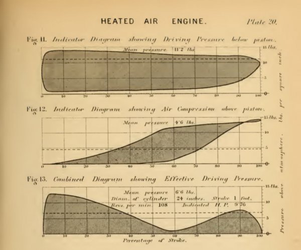
As soon as the pressure of the air in the pump begins to exceed that in the furnace, the delivery valve rises, and during the remainder of the stroke the compressed air is delivered from the pump into the furnace. When the piston arrives at the top of its stroke, the delivery valve closes; and when the piston begins to descend, there is a pressure of about 15 lbs. per square inch above it, and the body of compressed air being confined in a space of considerable capacity exerts a gradually diminishing force to about half stroke.
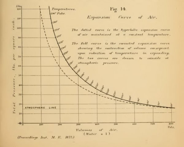
In calculating therefore the force required to compress the air, this return pressure in the downstroke has to be deducted in the measurement of the diagram. The difference between the mean pressure in the pump, as shown in Fig. 12, and the mean driving pressure below the piston, as in Fig. 11, is 6.6 lbs. per square inch, which represents the effective driving pressure, as shown in the combined indicator diagram, Fig. 13. From the fact of the engine being single-acting with a large cylinder, the friction, as might be anticipated, is very great compared to the power; for it is found that while the indicated horse power, as shown by the combined diagram, Fig. 13, amounts to 9.76, the actual working power obtained at the friction break is only 3.30 horse power.
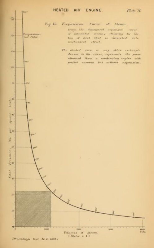
This air engine has proved very successful for cases where a small amount of power is required, and has the advantage of working for long periods without requiring attention either for firing or for the engine, and with freedom from the risk of explosion or fire attending the use of a steam engine.
The actual temperatures of the air have now to be considered, first at its entrance to the cylinder from the furnace, and secondly upon leaving the cylinder at the exhaust after performing its work.
The temperature of the air upon leaving the furnace was ascertained by one of Mr. Siemens' electrical pyrometers, which he most kindly placed at the author's disposal for the purpose of these experiments.
The instrument was fixed into the curved pipe Q, Fig. 4, leading from the furnace to the cylinder, the pyrometer itself being inside the pipe, about half way between the furnace and the cylinder. A more convenient mode of measuring temperatures can hardly be imagined, the indicating instrument being placed in the office many yards from the engine to be tested, and connected with it by a conducting cable; thus the observer was far removed from any annoyance or heat from the engine, and all he had to do was from time to time to send a telegraphic enquiry to Mr. Siemens' " salamander," whose post was in the hot-air pipe Q, and an answer was instantly received giving the temperature of that great heat with perfect accuracy.
From the average of a series of readings it was found that the air entered the working cylinder at a temperature of 1127° Fahr., equal to the dull red heat of an ordinary open fire. The average temperature of the air as it leaves the cylinder, ascertained by a mercurial thermometer placed in the exhaust port, was found to be 466° Fahr., a temperature at which steel acquires a pale straw colour, and about
16° above the melting point of tin.
It thus appears that 661° is absorbed in doing the work, and 466° or nearly 40 per cent of the whole heat is thrown away in the exhaust.
With regard to the consumption of coal, in these engines of one horse power it is found to be about 80 lbs. for ten hours work, or 8 lbs. per horse power per hour. It thus appears that, even with the wasteful system of discharging the highly heated exhaust air, without any means of recovering the heat and utilising it by making it warm a regenerator through which the cold air delivered into the furnace from the air-pump might be passed, these engines can yet compete successfully with small steam engines in economy of fuel; and if a regenerator were added, and every arrangement were carried out to obtain the best theoretical effect due to air expanded by heat as a motive power, these engines would equal or surpass in economy of fuel the results of the best engines worked by steam.
The difficulties met with are chiefly of a practical nature, and may be ultimately overcome, as several of them have been already in the engines now at work.
No allusion has been made in this paper to engines worked by gas, by gas and air, or by steam and air ; in fact only those heated-air engines that seem to have played a characteristic part in the history of the subject have been described.
When it is stated however that during the last half century upwards of 250 plans have been brought out for the application of air expanded by heat as a motive power, it will be seen how much attention the subject has received ; but undoubtedly the first practical scientific application of the dynamical theory of heat is due to Mr. Siemens, whose name is so intimately and so honourably associated with the rise and progress of that great discovery of modern science.
He was one of the very first who enunciated and demonstrated the conversion of heat into mechanical force, and in his regenerative steam engine a practical record remains of the strength of his convictions as to the truth of that theory at a time when it was received by only a few prominent physicists, such as Helmholz and Mayer in Germany, and Joule, Thomson, and the late Professor Rankine in this country; and it is an interesting fact, as showing the correctness of his reasoning, that Mr. Siemens' remarkable paper upon the conversion of heat into mechanical effect, though read before the Institution of Civil Engineers in 1853, just twenty years ago, is as much in accordance with modern scientific thought as if it had been written in the present year, and indeed contains nothing that new discoveries have not tended to confirm.
It now only remains to the author to acknowledge his obligations for the assistance rendered him in the preparation of this paper: to Mr. Wenham, for extensive notes and data supplied for the purpose; and to Mr. Siemens, to whom the author is indebted for much valuable information, and especially for the use of the very beautiful electrical pyrometer with which the temperatures were ascertained, and without which only a rough and scarcely approximate result could have been arrived at.