Shaw's Hot Air Engine
Source: The Engineer, p 137
Date: February 28th, 1862
Title: Shaw's Hot Air Engine
In this invention, by Philander Shaw, of Boston, U.S., two single-acting cylinders, having their pistons coupled to a shaft, with its cranks at right angles with each other, are arranged with a furnace and its accessories centrally placed between the cylinders and within an air-tight casing, which forms a reservoir for compressed and heated air, and is so divided by partitions and diaphragm plates as to receive the cool supply air at or near the exterior of the reservoir, and to guide it inward toward the furnace in such a direction that it shall absorb the heat radiated from such parts of the engine as receive the products of combustion, those parts of the cylinders in which the pistons fill the bore being located without, and upon the casing, and exposed to the atmosphere, and the other parts of the cylinder being located within the casing, so as to impart the heat radiated from them to the compressed air on its passage to the furnace.
The invention consists, secondly, in a peculiar construction and arrangement of the hot air cylinder, the packed part of its piston, and a piston trunk which, with the necessary packing valves and other adjuncts, form a pump, by which cold air is compressed and supplied to be expanded by heat, the pump being annular and exposed to the cooling influence of the atmosphere, and being operated by the direct pressure of the expanded air on the engine piston (when compressing the supply air), the force necessary for that purpose is not passed through the rotative parts of the mechanism, and facility is obtained for connecting the pitman which vibrates within the trunk direct to the piston, and for keeping the connecting joint cool by free atmospheric exposure, with good facilities for lubrication.
Thirdly, in a construction of the cylinder, which consists in a groove formed around the inner side of the cylinder at that part where the lower edge of the closely-fitting portion of the piston comes at the lowest point in its downward stroke, which groove serves to receive the lubricating fluid which escapes past the packed portion of the piston, and also such as may be directly introduced into it by means of "oil pumps", etc. The lower edge of the piston may be made to dip in the fluid in the groove, and so lubricate the inner surface of the cylinder at each upward stroke of the piston.
Fourthly, in the construction of an inwardly projecting flange, which flange may form part of the boundary of the circular groove above referred to, and comes nearly but not quite into contact with the contracted and extended part of the piston, for the purpose of deflecting such solid products of combustion as may find their way with the gaseous products into the space within the cylinder, and thus prevent them from abrading the finished upper part of the cylinder.
Fifthly, in the employment of an auxiliary valve operating to admit from the supply pump or receiver comparatively cool pure compressed air into the clearance space within, and connected with the cylinder for the double purpose of balancing the pressure on the inlet valve into the cylinder, and to maintain the frictional surfaces of the piston and cylinder cool enough to be kept lubricated. When the isolated oil trough is employed the cool air passing round it from this auxiliary valve cuts off from the oil the conducted heat which might otherwise evaporate it.
Sixthly, in regulating the speed of hot-air engines by controlling the flow of the air, under pressure, to the engine pistons, by means of a regulator operating to work a valve for this purpose, instead of permitting the regulator to open a valve for the escape and consequent loss of the generated pressure, as formerly practised in regulating the speed of hot-air engines.
Seventhly, in the employment of a close receiver for the "exhaust", with a large radiating surface within the air-tight reservoir into which air is forced, and then expanded by heat for the purpose of imparting from its outer surface a portion of the caloric contained in the "exhaust" to the surrounding currents of incoming compressed air.
Eighthly, in the utilisation of the caloric escaping with the "exhaust," by employing it to generate steam, substantially as described, which, when generated, may be made to operate through any well-known steam engine and air pump to aid in the compression and supply of air to the caloric engine, or the steam thus generated may be employed in any well-known way.
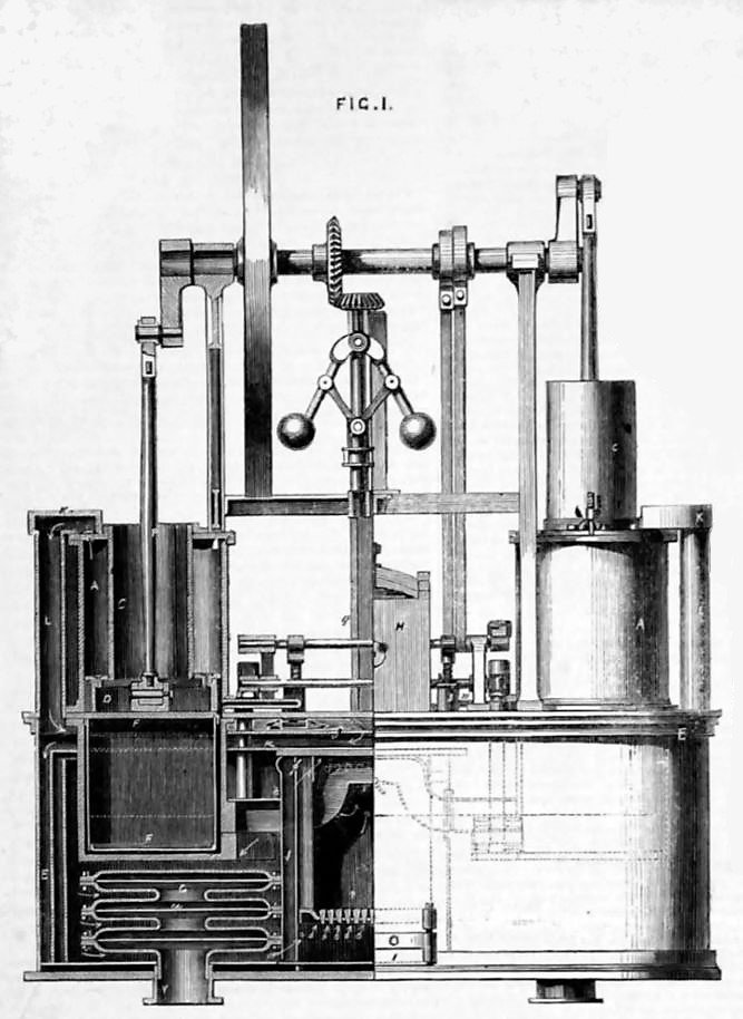
Fig. 1 illustrates, in half-side elevation, and in half-sectional elevation, a hot air of caloric engine embodying the invention, the section being taken in the lines y, y, Fig. 2, and z, z, Fig. 3.

Fig. 2 is a half plan and half horizontal section taken in the lines z1, z1, Fig. 1, and z2, z2, Fig. 2.

Fig. 3 is a sectional elevation of boiler designed to be connected with the exhaust of the hot-air engine to utilise the escaping heat.
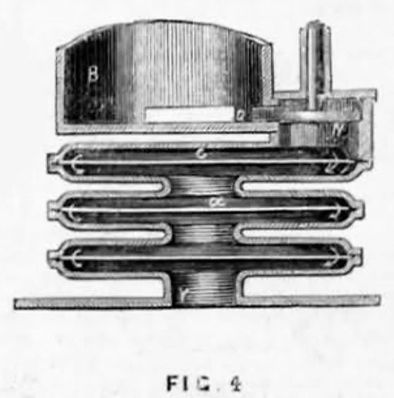
Fig 4 is a sectional elevation taken in the line y2, y2, Fig. 2, of so much of the cylinder and parts connected therewith as to illustrate how the exhaust escapes into the radiator or heater;

Fig. 5 shows in section the groove in the cylinder, the isolated oil trough therein, and inwardly projecting flange. E is the casing, which, as it forms the reservoir for he compressed heated air, the foundation or bed-plate for the mechanism should be so made as to be air-tight under the heat strains and pressure to which it is subject, and wherever moving parts pass through it they should be carefully packed. Centrally placed in E is the furnace lined with the firebrick J, provided with grates c, and an ash-pit, which has an air-tight door I, and fuel holder H, from which fuel is fed to the fire through the to of the furnace.
The fuel box H is provided with an air-tight receiving door d, having suitable fastenings, and a valve e, opened and closed by a link f and valve rod, which passes through a packing box. A piston g, with its rod h2, passing packed through H serves to thrust the fuel forward, so that it will fall through the aperture which the valve e serves to close.
By this arrangement and its proper manipulation, which needs no explanation, it is obvious the fire may be replenished with fresh fuel while there is the requisite pressure of hot air within the furnace needed to operate the engine, and without impeding the movement thereof.
The furnace is provided with openings a1 below the grates, and others a2 above the top of the fuel, through which air under pressure is supplied by means hereinafter to be described, which air is introduced into the space contained between the outside casing b of the furnace, and the casing t which next surrounds it.
The working cylinders, of which there are two, are located within and upon E, and on opposite sides of the furnace. These cylinders are single acting, that is, the piston of each is forced upward by the action of heated air, and both being connected to the same shaft R by cranks at right angles with each other, the downward movement of each piston is produced by the upward movement of the other, acting through the shaft in connection with the fly wheel.
Each cylinder may be described as in two sections, the upper section A standing above the bed plate, and being bored out so that a packed piston D may move freely therein after the manner of steam engine pistons within their cylinders.
The lower section B is within the bed-plate, for the reception of the extension F of the piston, and need not be bored or finished, as the extension of the piston is not intended to fill the cylinder, but leaves (when the piston is at the extreme of its downward stroke) an end clearance as well as an annular space around it.
That part of the piston which is marked D is constructed nearly like steam engine pistons so far as packing is concerned. The follower c1 is the flange of the pipe or trunk C, which is open at the top, and in which the connecting rod P plays.
The trunk passes through the upper head of the cylinder, where it is packed with leather, and guided by the gland x.
The head i is furnished with valves n to admit air into the annular space between A and C, and with an outlet valve o, which permits, when open, the air within the space in pass into the casing through the valve box K and pipe L.
Supposing the engine to be in motion, the air which is taken in by the pumps at each downward stroke of the pistons, is compressed and thrown out by the upward strokes thereof, and passes, as is indicated by the arrows, along the division plate j, which extends entirely across the space enclosed E, to an opening in the centre of j, then between plates j and k, then downward between the outer wall of E and an internal vertical partition m parallel with E, which extends entirely around within E, and parallel to its vertical wall, then vertically between partitions m and l, into a space contained between l and t, whence the air passes to the furnace through openings in t, and the openings a1 and a2 before described, the position of the damper r determining the proportion of air admitted above and below the fuel.
Having described how air is compressed and forced into the furnace, it may now be shown how, when expanded by heat, it passes into the cylinders and is exhausted therefrom, thereby producing reciprocation of the pistons within them, and developing the power generated by heating the air. In the top of the furnace, and passing through it to the inlet valve boxes O, is a suitably shaped pipe with an opening into it, which a throttle valve p operates to open and close in the usual way by a governor Q, dependent on the speed of the engine, and acting through the connection q.
The heated air and gaseous products of combustion mingled pass into this pipe, and when the inlet valve is opened pass into the cylinder, and force the piston upward.
The inlet valve closes when or before the piston has completed its stroke, and the exhaust valve opens and permits the contents of the cylinder to escape into the open air through the passage N, and radiator or heater G, placed in the space through which air passes on its way to be heated in the furnace.
The valves are of the poppet form, and are worked at proper times by lifter toes on the valve rods, and on rocker shafts worked from eccentrics S, on the shaft. There is nothing peculiar about the valves or valve gear, and any other which is adapted to the ingress and egress of the heated air, and known to engineers in the practice of their profession, may be used for those shown.
The form of the heater is immaterial; that shown presents a large surface for radiation, and the diaphragm plates a compel a tortuous passage of the "exhaust".
It will be seen that the disposition of division plates and partitions, before mentioned, is such as to cause the gradual heating of the cold air on its way from the pump to the furnace, by absorption of the heat, which radiates from the part of the cylinder filled with hot air, from the conveying pipes, heater, and boundaries of the furnace, so that the radiated heat is nearly all utilised, and the convenience is attained of having a comparatively cool surface to the outer or exposed parts of the machine.
A dead air space is formed in E between its base plate and the reservoir of compressed and heated air to prevent radiation from the lower surface. At the junction of the upper and lower sections A and B, of the cylinder, and at the lower edge of the close-fitting part D of the piston, a groove or channel v is formed entirely around the cylinder, as shown in Fig. 1.
At the upper edge of B there is an inward projecting belt or flange s, which forms the bottom of the groove and extends inward from the general surface of B, so as almost to touch he lower or extended part F of the piston. The groove or channel round the cylinder communicates with the compressed air in the upper part of E, by means of the pipe E, which terminates in the valve box b1, in which the poppet valve u operates by any suitable mechanism, that shown being a wiper or arm on a rocker shaft acting on the valve stem, to open the valve against a spring, the reaction of which closes it.
It will be seen that when the valve u is opened air will flow from the space in E, above j, into the cylinder, and if this valve is opened, as it should be, after the exhaust valve closes, and before the main inlet valve opens, that all clearance or unoccupied space in the cylinder and valve passages will be filled with air having a pressure equal to that within the air reservoir. The air taken into the cylinder through the valve u will be that directly from the pump, and free from gaseous and solid products of combustion, and moreover it will be comparatively cool.
The object of introducing air through w, from and at the places and at the time mentioned, is threefold.
-
First, by rendering the pressure alike on both sides of the valve, the force required to be exerted is reduced to the minimum.
-
Second, by having the spaces in the cylinder filled with pure air, that which rushes into the cylinder from the combustion chamber, to displace the piston, will not carry the products of combustion into the spaces so occupied, and as the valve u and the main inlet valve are designed to be closed together, it will be evident that the annular space between the extension part F, and the upper or finished part A of the cylinder, formed as the piston rises in the cylinder, will be kept filled with pure air, to the exclusion of the impure air, which will fill the body of the cylinder.
- Third, the packing of the piston will thus be exposed at its upper and lower edges to cool air, while the sliding surface of the packing will act upon that part of the cylinder which is exposed both upon its interior and exterior to air of the ordinary temperature.
By the described arrangement and devices, the patentee is enabled to pack the piston as closely, and to keep it as well lubricated as any steam engine or air pump piston.
The inwardly projecting flange s serves to deflect or render difficult the passage of any particle of solid matter coming into the cylinder with the heated air and gaseous products of combustion, and the lower edge of the packed portion of the piston is of the form shown in Fig. 1, to aid in deflecting solid particles to keep the sliding surface of the piston from abrasion by them.
The groove v around the cylinder serves to catch the oil which passes the packed piston, or oil may be forced into it by a syringe, and a pipe provided with a stop-cock will afford means for drawing off any accumulation of lubricating material which may gather there, while the lower edge of the packed part of the piston, by dipping into the oil at each downward stroke, will aid in keeping the working surfaces well lubricated.
To prevent burning the oil by the heat absorbed and conducted by the material of the cylinder, there is placed within the groove a circular oil through M, Fig 5, which is maintained at a little distance from the metal of the cylinder by ears placed at intervals around the trough; the current of cool air from the auxiliary valve will pass through this space and around the trough M, keeping the oil at or about the temperature of the air in the casing E, above the division plate J.
One of the many forms of boiler which may be employed to utilise the caloric in the exhaust is illustrated in Fig. 3, where a plain vertical tubular boiler U is shown set in brickwork with a furnace beneath it, for a purpose to be explained hereafter.
The "exhausts" pass into a smoke-box at the top of the boiler through the passages Y, Y, which can be closed by the dampers therein shown, and, after passing through the tubes, escape through the outlet w, which is provided with a damper, the direction of the currents of the exhausts being indicated by the arrows.
As this boiler may be made available in starting the caloric engine, a fire to generate steam may be kindled on the grates shown, and the dampers in Y and W closed, when the draft will be in the direction indicated by the dotted arrows, escaping past the damper v in the smoke outlet.
The steam thus generated may be employed in an engine to work an air pump to compress air into the reservoir E, and to support combustion on the grates c of the furnace within the casing, or the engine which uses the steam may be coupled direct to the shaft R, to rotate it, and thus compress air into E, and support combustion on grates c, by the action of the before-described annular air pumps.
After the fire is will agoing on the grates c, and air compressed within E, the expansion by heat of the compressed air will work the caloric engine without any external aid, and the fire kindled on the grates beneath U, may be permitted to die out.
The dampers in Y, when any are used, should be opened before the shaft R is rotated, and the door of the furnace under the boiler and the damper V, should at the same time be closed, while the damper in W should be opened.
In small caloric engines constructed in accordance with this invention, and where the shaft R can be rotated by hand or otherwise sufficiently to compress the air within E, it may not be worth while to attempt to utilise the heat escaping in the exhaust, by applying it to generate steam, but much may be utilised by increasing the area of the radiator G, which may be entirely dispensed with when the boiler U is employed, substantially as described.
In starting a fire on the grate c, the main inlet exhaust, and throttle valves, and ash-pit door should be opened, and also the dampers in the exhaust exits Y, so that the products of combustion may be carried off through the engine.
If the draft by this passage should be insufficient to make the fire burn freely, then the valve e should be opened, and the door d taken off, thus establishing a direct upward draft, which may be conducted by a temporary funnel.
When the fuel is well ignited, the doors J and d, the exhaust and main inlet valves, should be closed, and if the steam boiler is connected, the dampers should be manipulated as before described. Air should then be supplied to the fire on grates c, and compressed and expanded within E, by any of the means mentioned, and by the fire on the grates, when sufficient pressure will be generated to move and maintain in movement the pistons before referred to, while the fire can be kept supplied with fuel by the described means.
It should be observed that the valve chest covers are provided with pipes T, as shown in Fig 5, which extend up through the top of E, where the pipes and the valves stems can be packed, without having the packing exposed to heat that would be destructive to it.