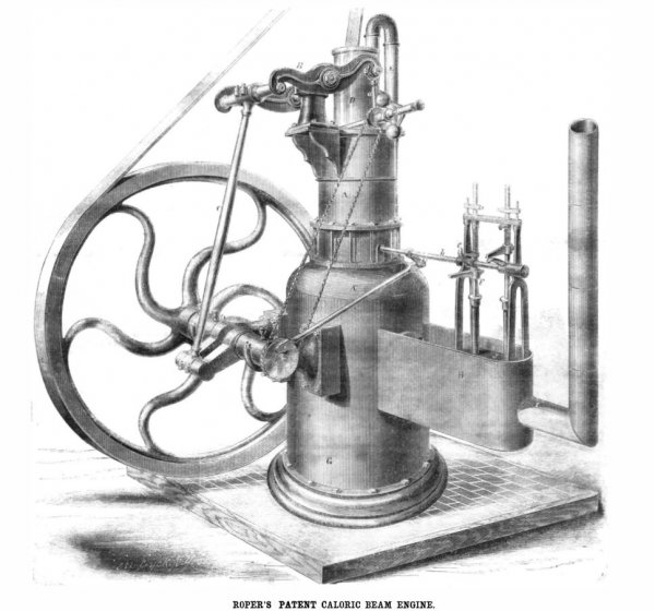
Roper’s Caloric Beam Engine
Source: an article from Scientific American, Vol. VIII, N°7.
Date: February 14, 1863
Title: Roper's patent caloric beam Engine
Roper’s Patent Caloric Beam Engine
The employment of caloric engines has latterly been confined to light duty and to those manufactures which do not require the development of an immense power. They are also coming into favor for domestic and agricultural purposes, as, for example, pumping water, cleaning grain, sawing wood and a multitude of other operations for which they are eminently suitable.
They are easily managed, are clean when running, they require no water, and are very economical in respect to fuel; and lastly, though by no means the least consideration in these tight times, is the fact that the rates of insurance are not increased by using them in any building.
The one from which our engraving is taken is novel, in so far that it is the first attempt, to our knowledge, to use the general features of a modern beam engine for caloric purposes. The relations of the several parts with reference to each other will, we think, be readily understood by the letters and sub-joined description.
The cast-iron cylinder, A, is bolted to the chamber, A”, situated directly over the fire-box and separated from the same by a partition.
The pillow block carrying the working beam, B, is bolted to the brackets on the side of the cylinder.
The piston of this engine has two side links, a, which connect to the two ends of the working beam; through them and the beam power is transmitted to the shaft by the connecting rod, C. The air pump, D, is situated over the center of the cylinder and operated by a hollow rod common to both pistons.
The siphon shaped pipe, E, seen issuing from the cylinder at one side behind the air pump, runs down into the cylinder and is there put in connection with the piston, and fire-box below, by means of a telescopic or sliding tube fastened to and moving with the main vis ton itself. By this means the current of air which enters the piston from the air pump keeps it at a very even temperature.
The main shaft has a plate attached to one end which drives the induction and education valves, F, through the rockshaft, b, and toes, c.
The doors for supplying the fuel, which are perfectly air-tight, in the furnace, G, are on the opposite side from the reader, and cannot be seen in this view of the engine. There is an opening into this fire-box through which the heated and compressed air passes into a supply pipe in the box, H, connecting with the induction valve, F, a similar contrivance allows the air exhausted from the cylinder to issue through the flue, I. This flue is also the channel through which the coal gases, produced by the burning fuel, find their way to the chimney.
A portion of the air chest in which the valves work, is seen at J; the outer casing, H, is merely a protection to the hot-air pipes. These latter are covered with ashes or other non-conducting material, and the heat thereby prevented from radiating. The box, H, answers the same purpose as the steam jacket on a steam engine.
There are, also, upon the other side of the furnace, two small dampers which connect with the upper pipe, E, and change the direction of the air current at the will of the engine-driver, so that the air is directed upward through the burning fuel, or merely heated by passing over the surface, thus expanding its volume to a greater or less degree, as the load on the engine is increased or diminished.
This engine is rated at two-horse power; a cubic foot of air is supplied by the air pump, which is heated at every stroke. The cylinder is sixteen inches in diameter, and has sixteen inches stroke on the piston. The usual number of revolutions is one hundred, but they can be increased without difficulty to one hundred and fifty per minute if necessary.
The piston is packed with leather, which is kept from charring by the cool current of air constantly circulating through it when the engine is moving.
This engine is similar, in some respects, to an ordinary beam engine, and works almost noiselessly with great smoothness and regularity. The engine from which our engraving was made weighs about 3,000 lbs., and occupies about six square feet of space, and can be readily transported from one part of a building to another.
About 70 lbs. of anthracite coal are consumed in working twelve hours. We made no tests to ascertain the force exerted by this engine, but so far as a mere conjecture goes we should think it exceeded the power it was estimated at.
This caloric engine is the invention of Sylvester H. Roper, of Boston, Mass., and is covered by several patents recently issued. Further information respecting prices, &c., may be had by addressing Crosby, Butterfield & Haven, 22 Dey street, New York, or 47 Pearl street, Boston, Mass., where these engines can be seen in operation.
